Bladeless Fan
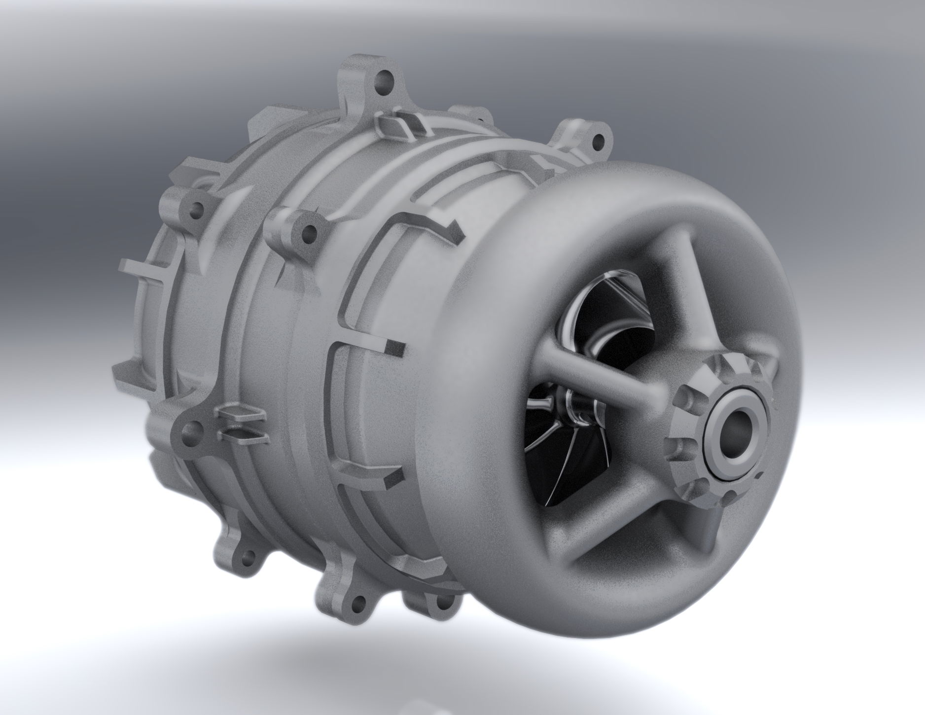
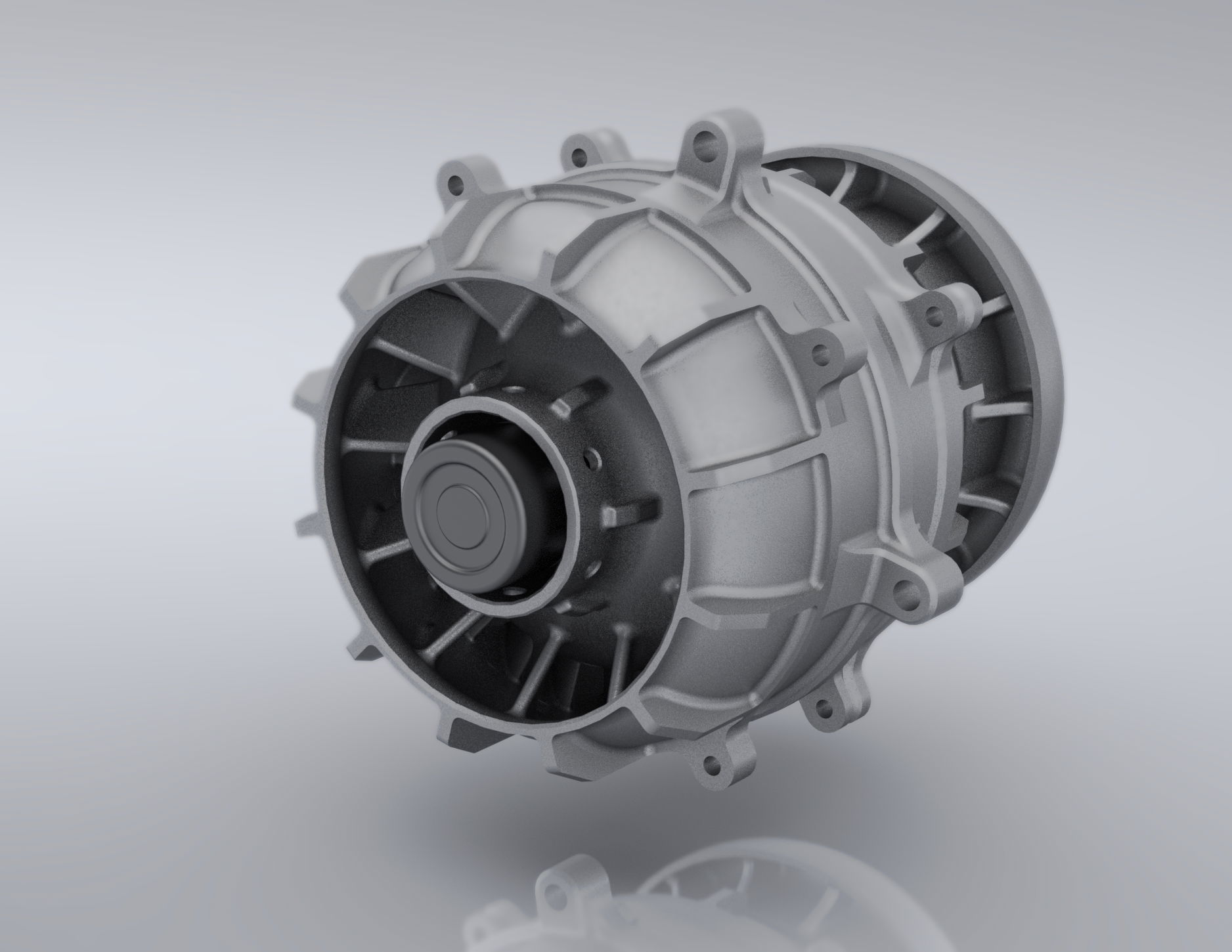
The aim was to understand how a Dyson bladeless fan worked as well as some of the physics behind it. To help accomplish this, I essentially reverse engineered the device, modelling the main important parts - the fan head (the recognizable ring shape) and the propulsion unit (the component that sucks in the air and blows it out). I would then endeavor to improve the impeller design which would have to be done through real life testing and iterations.

This diagram is probably quite easily one of the key concepts in this device. It is the Bernoulli's principle regarding the pressure and velocity of fluids - it states how that if the velocity of a fluid is increased, the pressure of that fluid will simultaneously decrease. This change can be caused by a changer in the diameter of the ducting. Put simply, the Dyson bladeless fan, simply consists of a fan concealed within the device, that propels air through the ducting which is the ring-shaped fan head. Regular fans create the airflow by using a large axial propeller to move air volume along but this bladeless fan does things a little differently. An impeller is used to create high pressure airflow within the device and this goes through the fan head ducting but is then forced through the thin slits. This change in the channel size, causes a drop in pressure but more importantly a large increase in air velocity, allowing the device to spew out fast air - in a way this is somewhat similar releasing air from a pressurized can.
Now, how is air pressurized before going through the fan head? This can be done through a number of ways. I mentioned that how it was similar to a leaking pressurized canister but using something like this is far from ideal.
- The hissing of air is loud
- Air would have to diffuse when entering the fan head ducting which would greatly reduce the velocity of the air. Due to not having a propulsion system, the performance of the air coming out of the outlet would be poor
- They use a small nozzle for air to exit the canister; the volume of air is far too low to fill the ring properly nor giving a good volume of airflow
- Requires a loud compressor
- Large volume taken up by the canistor
- Heavy
There are other reasons but just wanted to explain that it's definitely not a good choice. However, the way to achieve compressed air is to use a compressor. There are multiple types of compressors but normally involves an impeller (a ducted propeller) to do this. There are 2 main types of an impeller - radial and axial. Radial impellers suck in air axially but then its shape causes the air to blow outwards at a tangent to the axis of rotation. This type tends to feature a spiral casing called a volute, and stator blades to achieve high pressure air; radial impellers achieve high pressure but low air volume. The perpendicular change in direction causes the air velocity to reduce too. Axial impellers are basically the opposite, propelling air axially, obtaining high volume but low pressure. Stator blades can also be added to obtain compression but this is still weak compared to a radial impeller. However, it is possible to use a multi-stage axial compressor (just like a jet engine compressor) which will allow for high velocity, high pressure and high volume but is not ideal for this application due to: it's lengthy size, complexity and general difficulty to achieve high compression ratios when the compressor is so small. It is essential to have an impeller that has both high pressure and high air volume; high pressure is due to reasons explained before but high air volume is so that more air is shifted through the device, allowing for a larger flow of air like a normal fan, unlike an air canister which is has a small opening and small flow.
All is not lost.

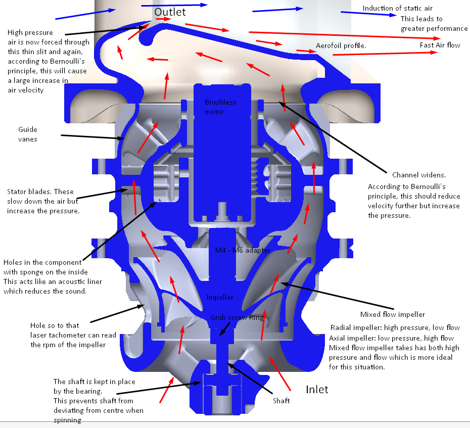
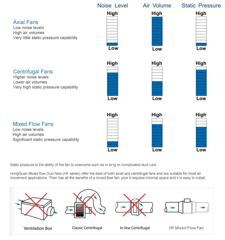 Luckily, there is also another type of impeller, known as the mixed flow impeller. It's named this due to its ability to have both axial and tangential characteristics, bearing a closer resemblance to a radial impeller but the angle is far more forgiving, allowing for faster air flow but also lacks a spiral casing volute, featuring an axial outlet with stator blades. As a result, the impeller achieves, high air flow and high pressure. This impeller type is the best option for the device.
Designing the Propulsion Unit:
Overall, there were 3 main different iterations of the propulsion unit. The final of which underwent further development due to having to solve problems that I ran into when making the device in real life.
Iteration 1:
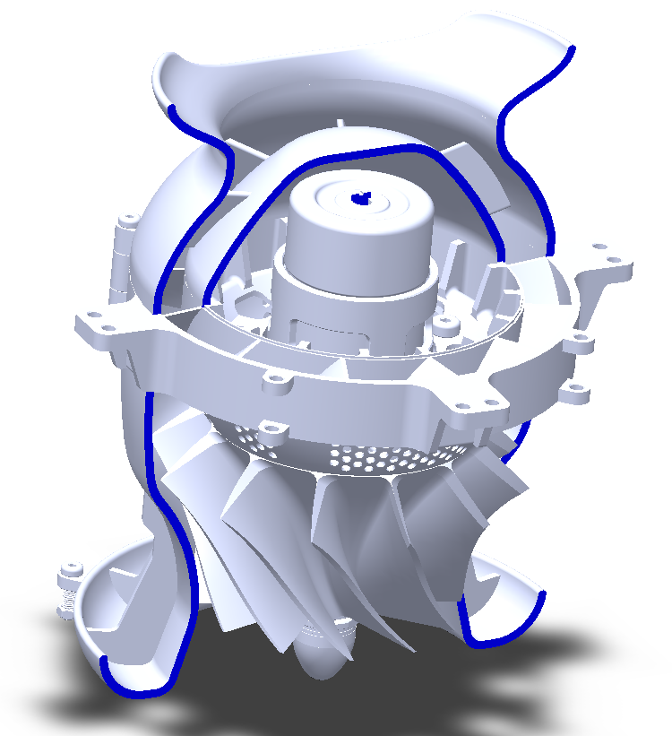
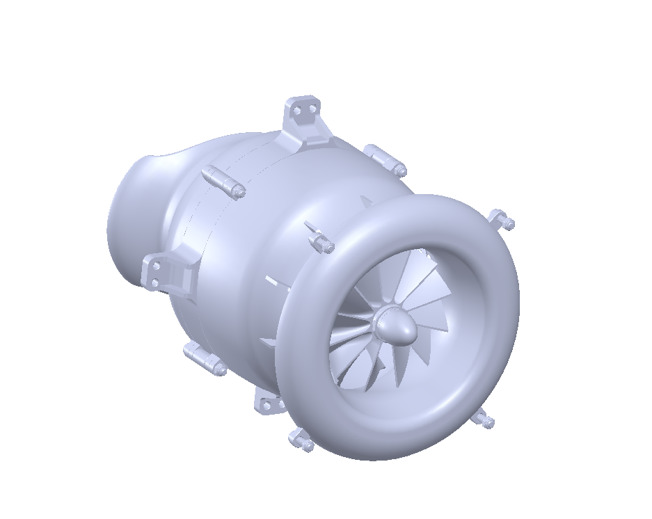
Iteration 2:
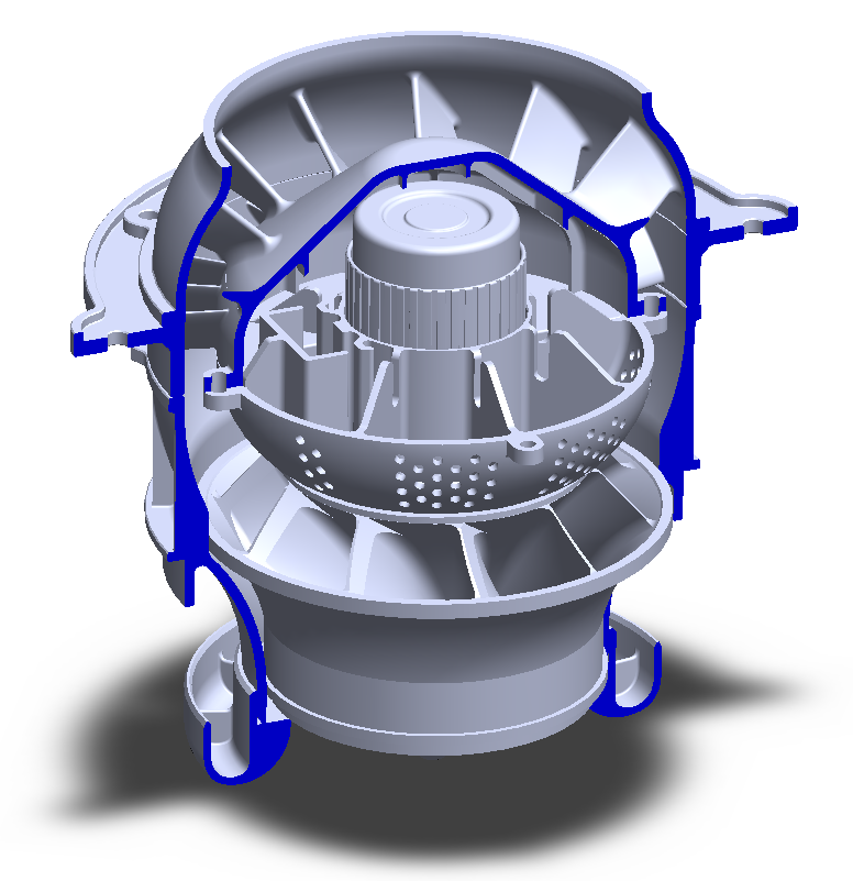
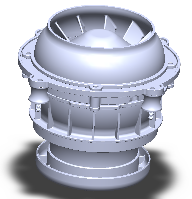
Iteration 3:
Propulsion Unit Prototyping + Impeller Testing:
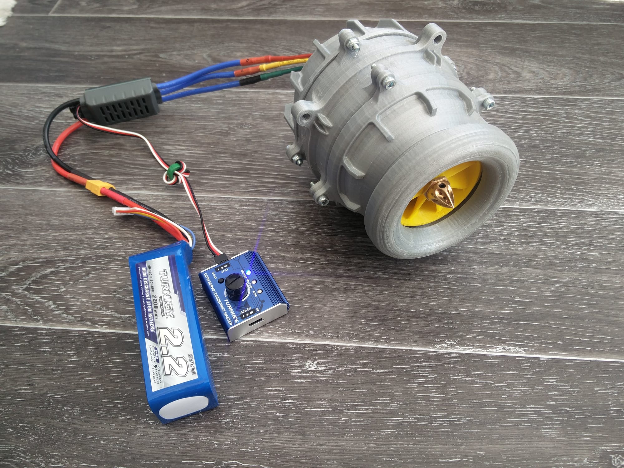
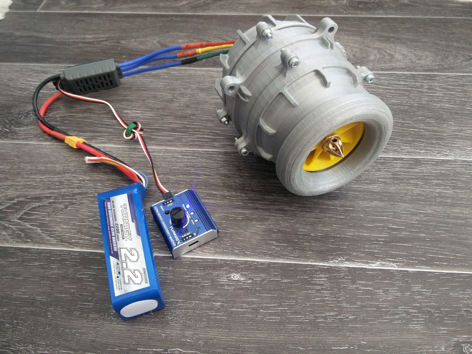
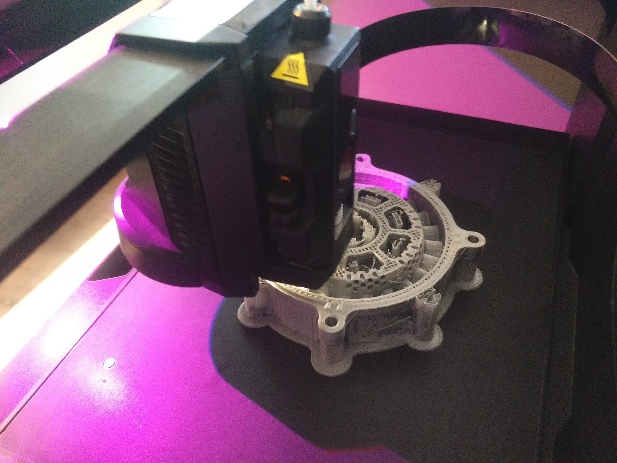
Under this section of the project, I 3D printed parts of the 3rd iteration of the propulsion unit with the aim of developing the impeller designs to see which one performed the best. Throughout this, a lot of issues came in my way and I had to redesign and replace parts to solve them. My progress and testing of this has be presented in this link: https://www.docdroid.net/55MsvDF/propulsion-unit-manufacture-impeller-testing.pdf
Some of the pictures in this project:
Final Design:
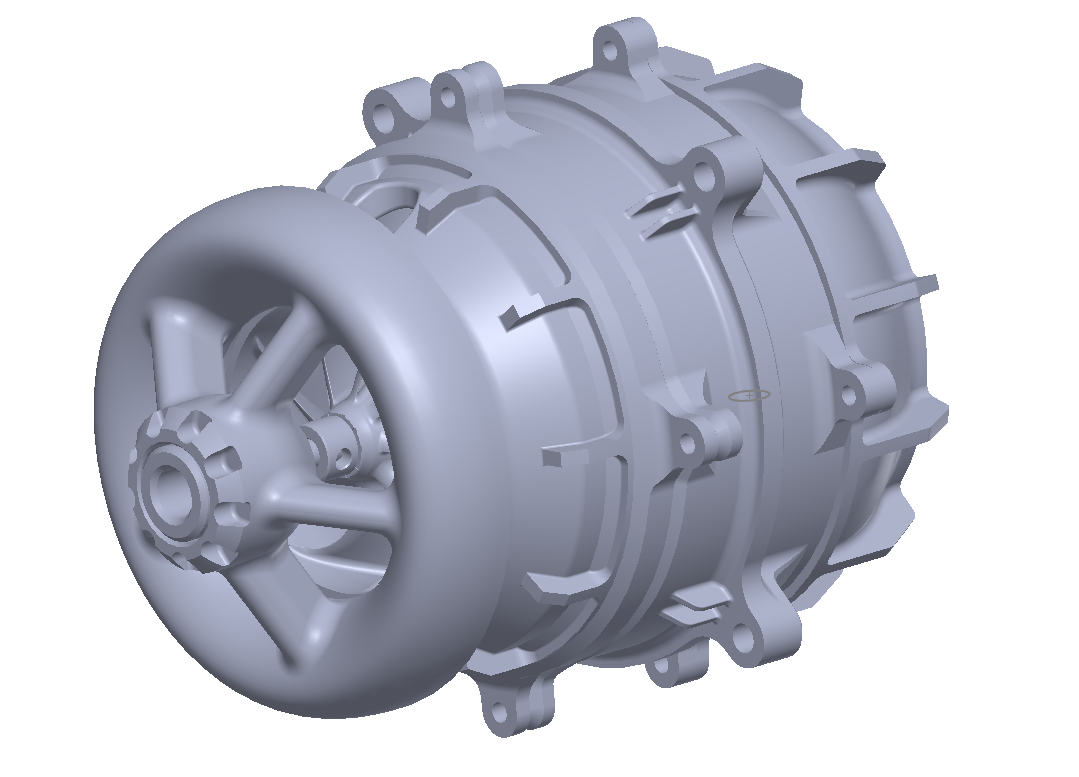
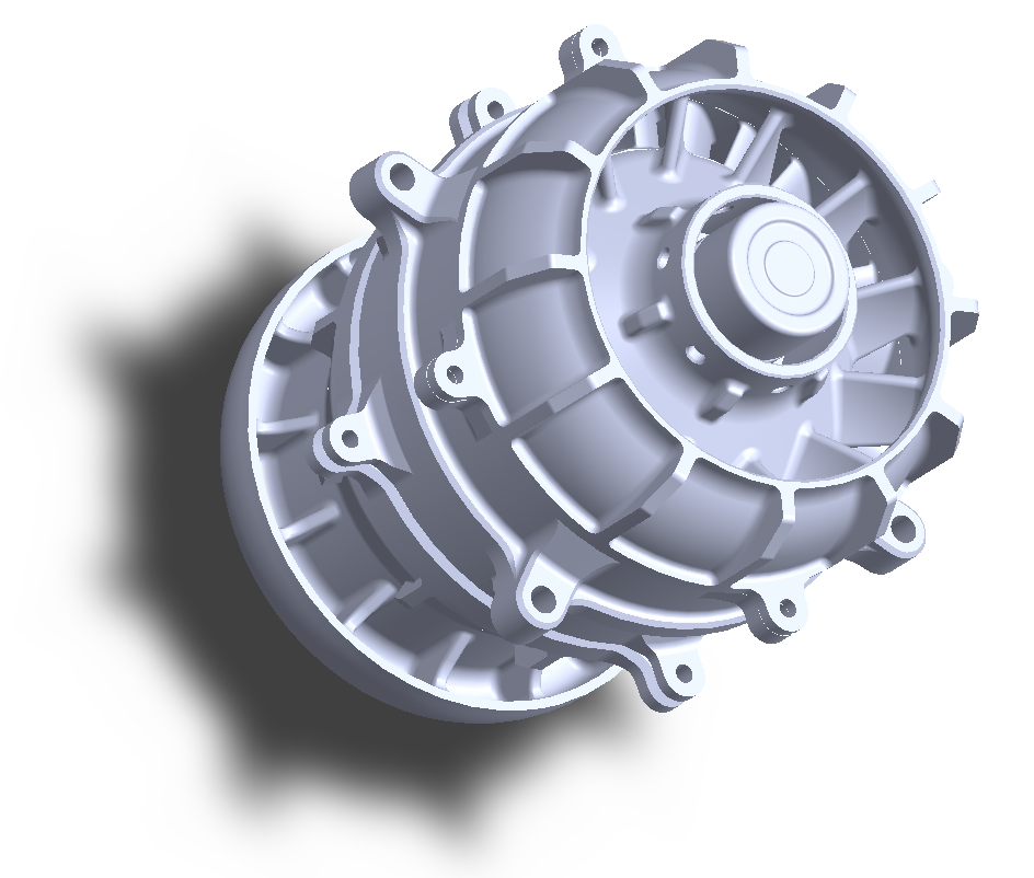
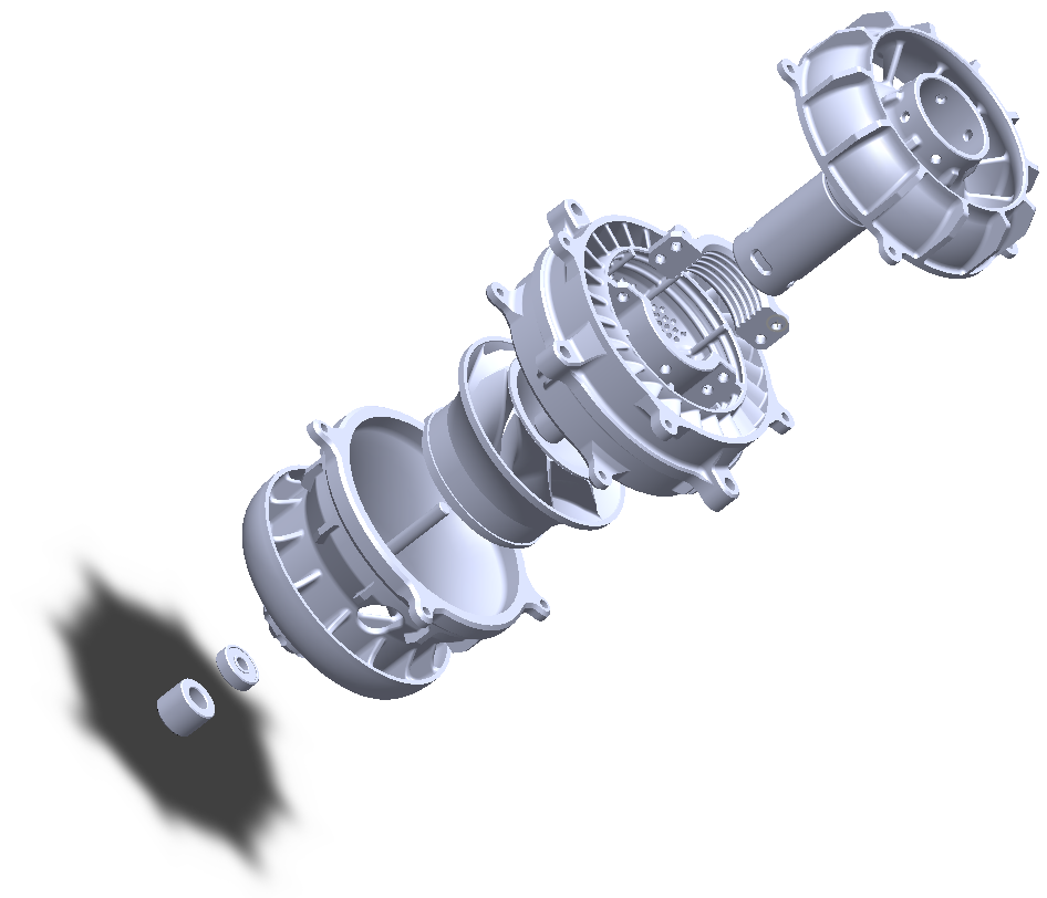
The final design was indeed adapted a little so that it could be 3D printed without issue, mostly just making certain features and walls thicker. The gap between the impeller neighboring parts were made larger since 3D printing has a lower tolerance but also just in case the impeller starts to wobble or the shaft is not fully straight.
The diagram below explains how the fan works. Note that this is using the very latest version of the final design.
Conclusion:
Overall, this project has taught me a lot with physics concepts, CAD modelling and iterative design. Whilst the set-backs and constant issues that needed solving were frustrating at times, the process of figuring out the best solution and modelling replacement parts was enjoyable and it is greatly satisfying to see one's CAD model come into real life. I had achieved my goal of designing the propulsion unit, understanding how bladeless fans work and finding the best impeller design through my testing.
