ME3 DMT - Biofuel Exhaust Heat Recovery & Storage System
Exhibition Poster:
PDF of detailed testing and analysis report:
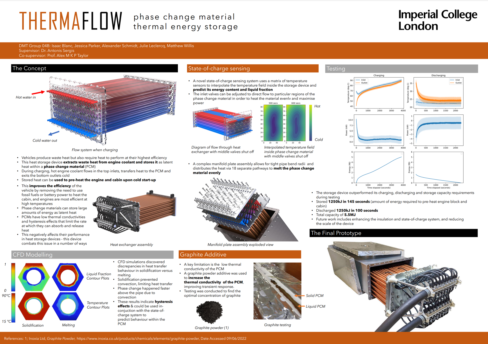
Combustion engines typically only makes use of around 30% of input fuel energy into actual effective power, leaving approximately 65% of the energy to be wasted through the exhaust gases and the engine coolant. This ME3 group project (team of 5 people) recognizes that recovering some of the energy lost as heat is a potential way to improve the efficiency of combustion vehicles. We've been directed to make use of a phase-change material thermal storage system to store the heat recovered from the engine. A PCM material is able to store significant quantities of energy due to the latent heat when undergoing phase-change, making this an ideal approach to store heat effectively. We aim to produce a prototype system to investigate this novel concept.
System Planning:
We first identified that the primary sources of heat are from the engine coolant (around 80-90C) and the exhaust gases (300+ C), low and high grade heat sources respectively. This indicates the necessity for a dual PCM system to take advantage of each. The two heat grades also allows a greater variety of applications of the stored heat. For example, the high grade PCM could be used to pre-heat catalytic converters upon cold-starts to ensure that the converter is performing sufficiently - an issue where typically the converter is too cold, leading to a significant quantity of a vehicles harmful emissions to occur. Meanwhile, the low grade PCM could be used for cabin heating or for heating up the engine in the event of a cold-start. The combination of all these applications will allow the vehicle to run more efficiently and produce less emissions. Additionally, this system has applications in hybrids/EVs where stored heat could be used to run cabin HVAC, improving battery life and vehicle range due to reducing the need for electricity for heating.
Original Planned System:
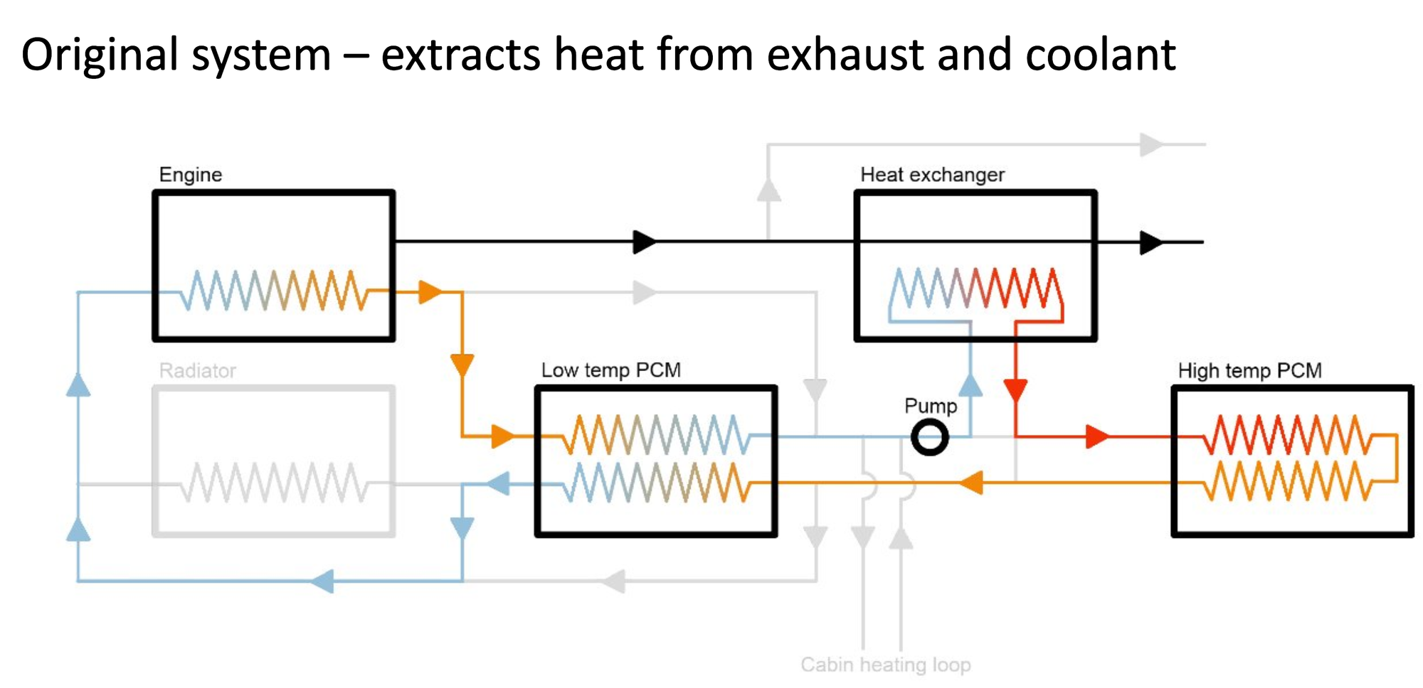 The image above shows a diagram of our original planned system. This involves taking the hot engine coolant to heat up the low grade PCM, where the now cooled coolant is sent through the exhaust heat exchanger, reaching significantly higher temperatures, to then heat up the high grade PCM. Whilst the coolant would cool down through the high grade PCM, it is intended to have sufficient heat to then further heat the low grade PCM. This system would allow for a significant extraction and storage of waste heat from the engine. To manage this system through its various modes of operations, a large number of bypasses are employed to reroute flow away from certain parts of the system or to discharge heat from a particular PCM unit to a particular application.
However, we found that this system was far beyond the scope of our provided budget and that it was unlikely the provided engine would be operational - which all forced us to simplify.
Simplified System:
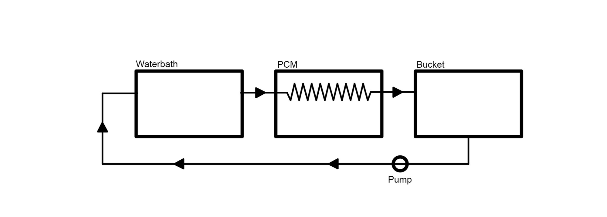
This simplified system scales back the design to a singular PCM unit and omits the engine as it would be unlikely to be fixed in time for our testing. Additionally, to save cost on components, materials and testing, we opted to keep the low grade PCM instead of the high grade PCM; this would take heat from the hot engine coolant.
PCM Choice:
We decided to use an organic phase-change material despite its slightly lower performance and higher cost due to a greater range of material compatibility and not being toxic/corrosive. We chose CrodaTherm74 which has a phase-change temperature of 74C, which gave the ability to be used for cabin heating as well as engine warmup.
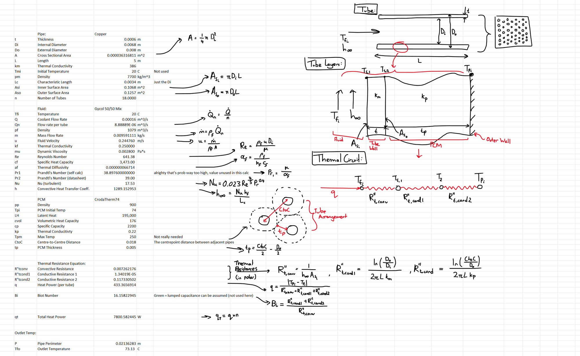
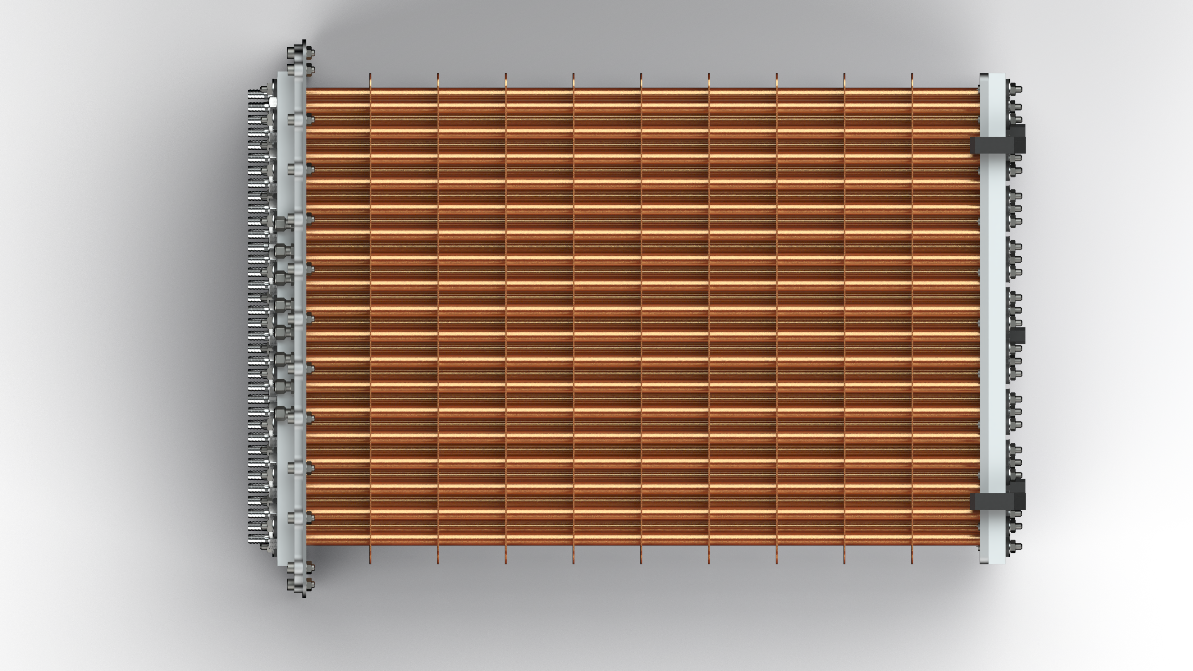
PCM Container Design:
The PCM container itself would effectively serve as a heat exchanger. The engine coolant pipe would split into multiple smaller diameter pipes which would form a zig-zag pattern within the PCM container chamber - where the pipes are laid in a form of triangular lattice to ensure greater pipe density.
Python Programming:
We started by writing up initial calculations in Excel which are used here to predict the outlet temperature of the coolant in the scenario of the PCM discharging its heat to cool coolant. We've also assumed that the PCM maintains a constant temperature during this.
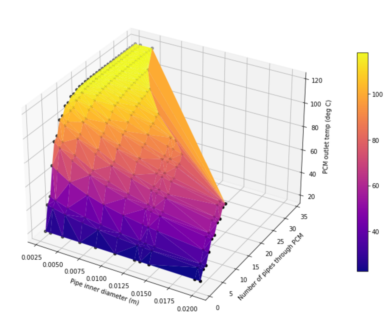
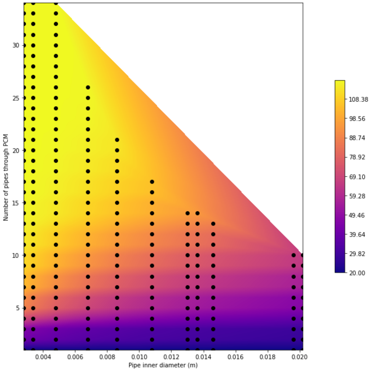
Our Python scripts are based off these Excel sheet calculations but applied across multiple heat exchanger configurations (as represented by the dots) to produce a surface shown below. We present this in both 3D and 2D forms and we used this to select our heat exchanger configuration.
Additionally, we produced a map to estimate potential back pressure by using a ratio of the cross-sectional areas. Though not accurate, this gives a good rule of thumb. 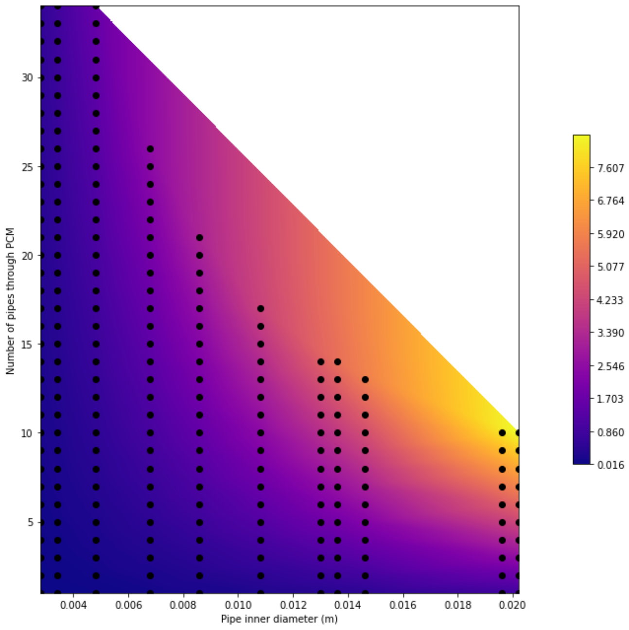
The creation of the configurations are also conducted by an additional script. For a given input container volume, PCM volume requirement, pipe diameter and pipe splits, the script is able to produce a configuration of maximal pipe density. It also displays the cross-section of the heat exchanger in the graph below.
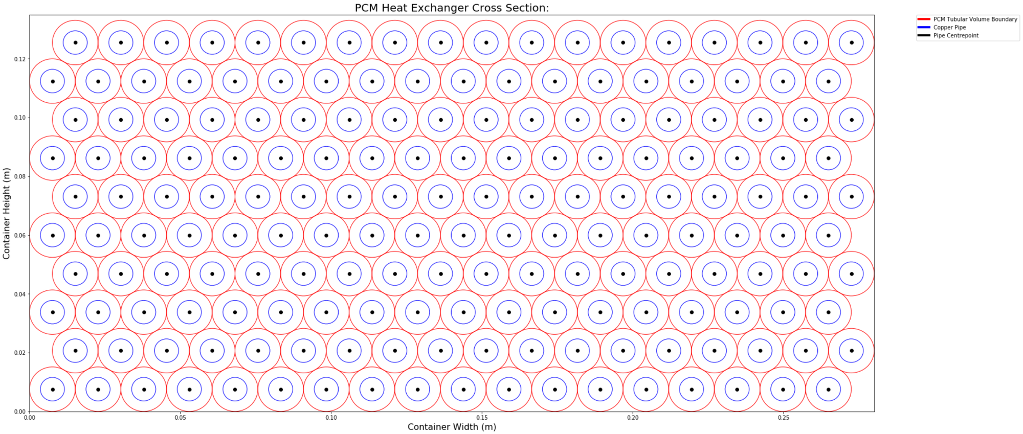
This script performs checks on whether there is sufficient PCM volume for our application and whether the pipes interfere with each other - from which configurations must pass both in order to then be plotted onto the graph.
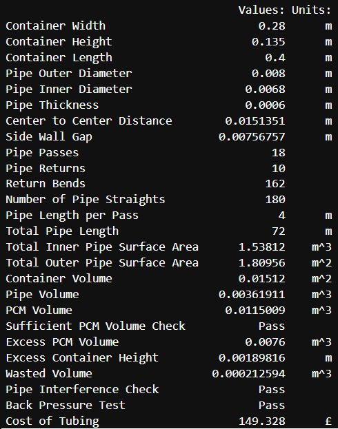 Additionally, the script also produces a variety of useful information and dimensions - instrumental in the CAD modelling.
Final Design:
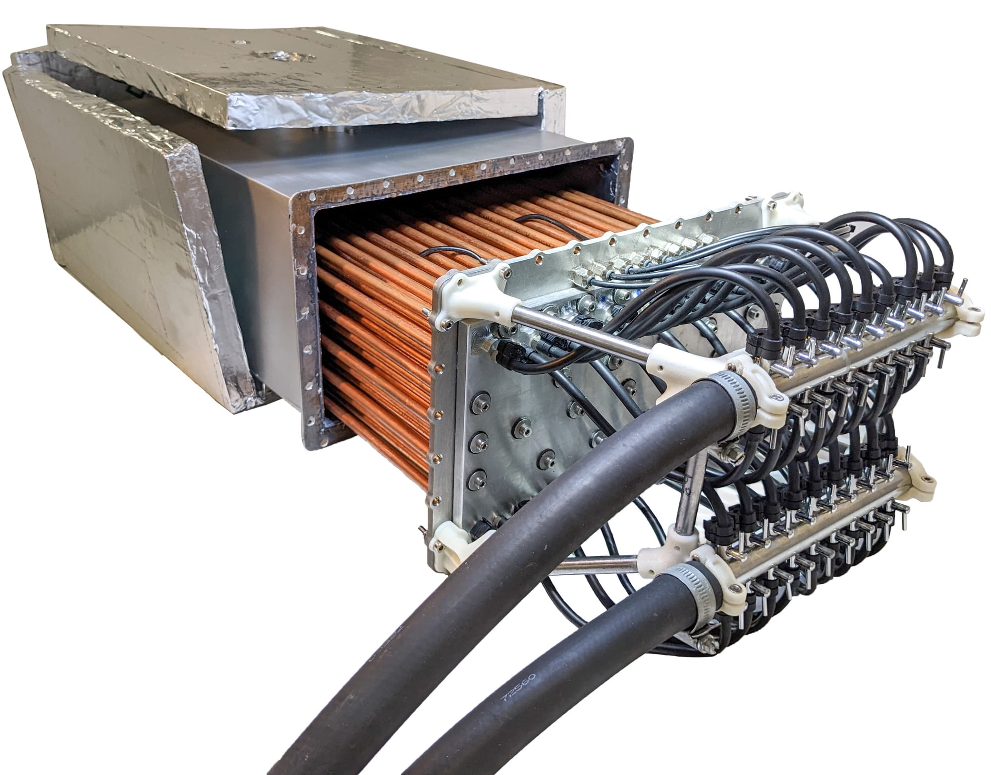
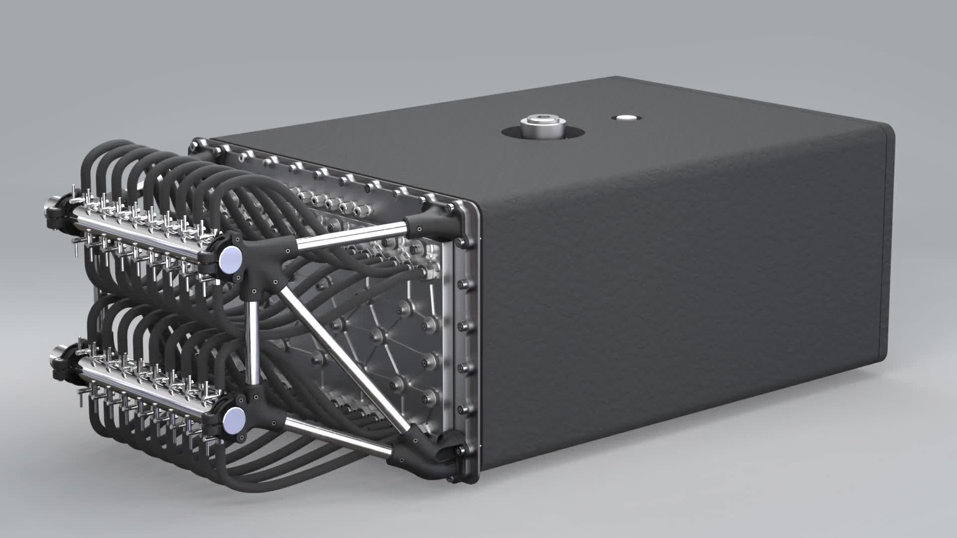
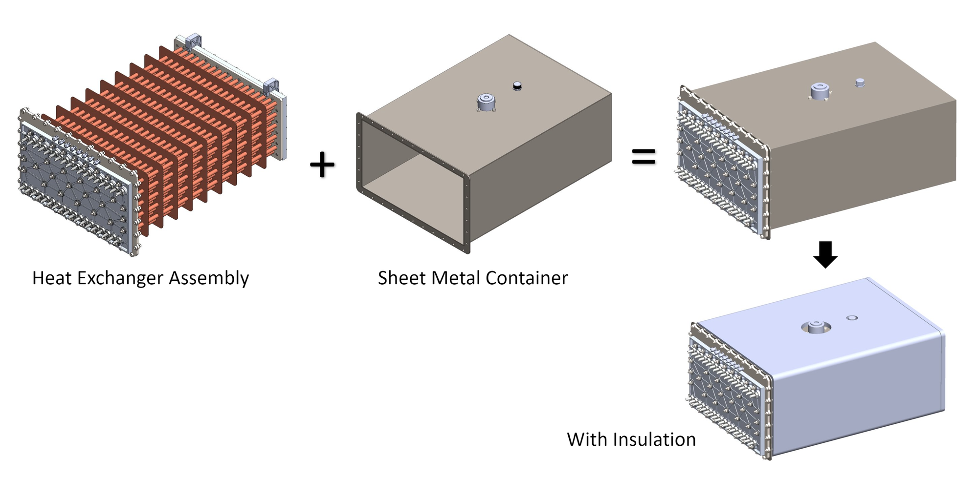
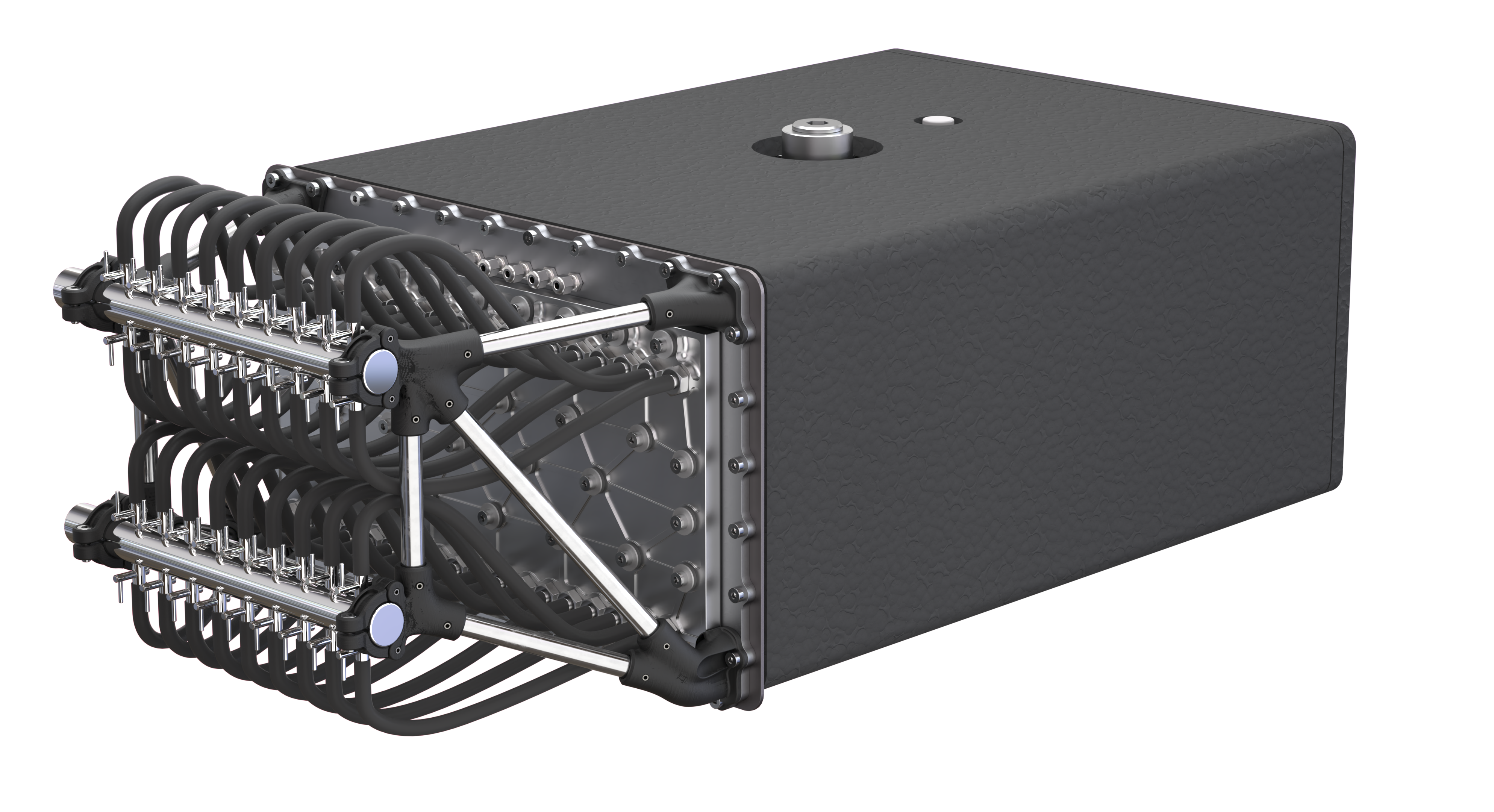
The final design underwent multiple variations before being finalized. We initially intended to have copper pipe bends through either purchasing pipe return fittings or bending the pipe ourselves. However, we found that we were unable to bend the pipe nor obtain return fittings at a low enough cost. So instead, we devised a manifold design at either end of the pipes which instead handle the operation of the return bends. Our overall design consists of the heat exchanger being slid into welded metal container, which is wrapped with aerogel insulation, as shown below.
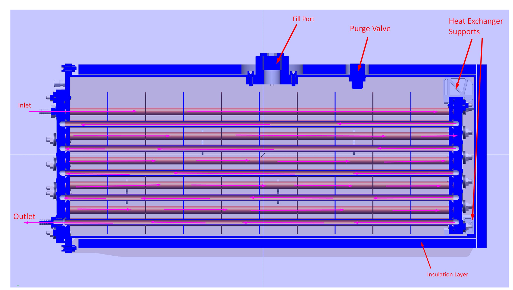
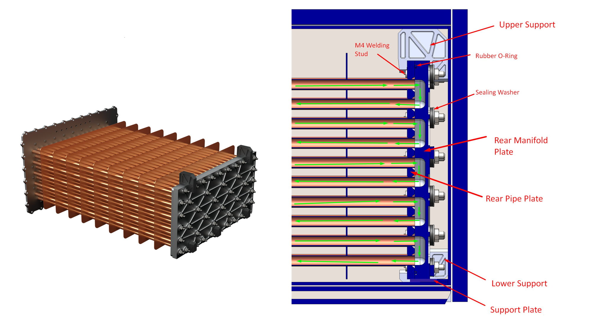
Side Cross-section:
This image below shows the cross-section, revealing how the heat exchanger assembly slides into the container. Nylon 3D-printed supports are used to allow the assembly to easily slide across the base of the container as well as provides support to the rear-end of the copper heat exchanger in the scenario that the entire system if flipped upside down or put upright.
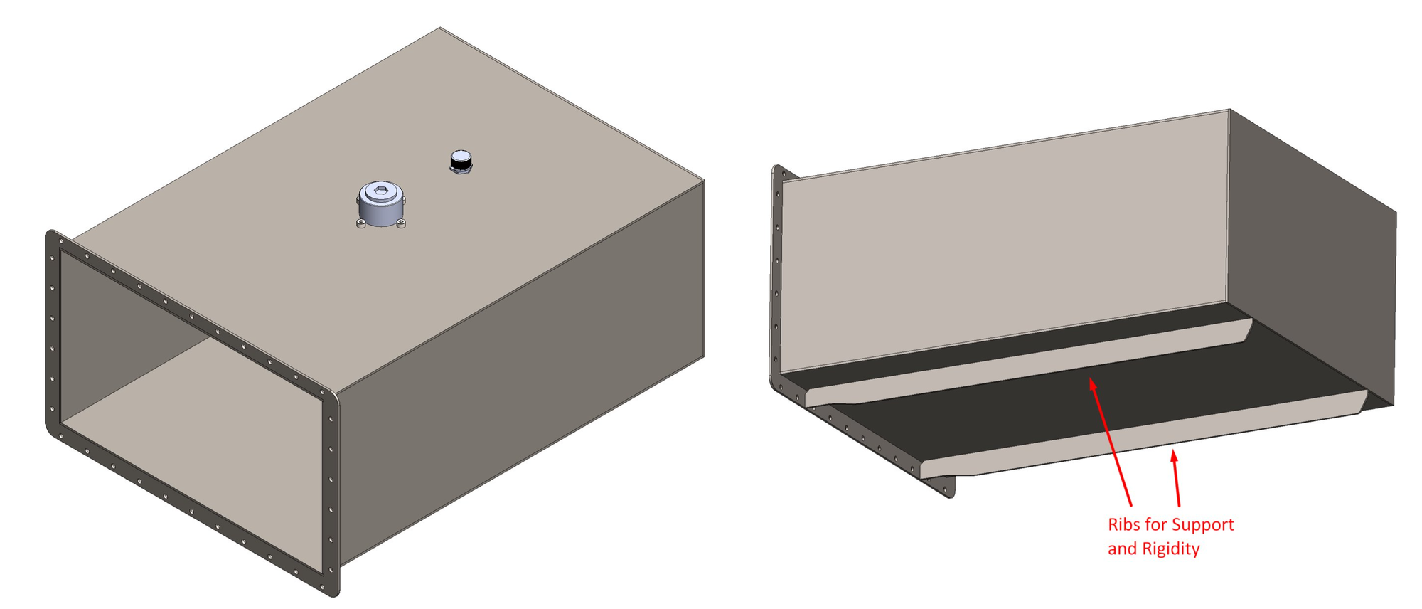
Metal Container:
These would be laser from a single sheet of mild steel, which was chosen for its lower cost and ease of welding. The issue of rust is put aside as this container only needs to last for the period of testing. The container also features a fill port
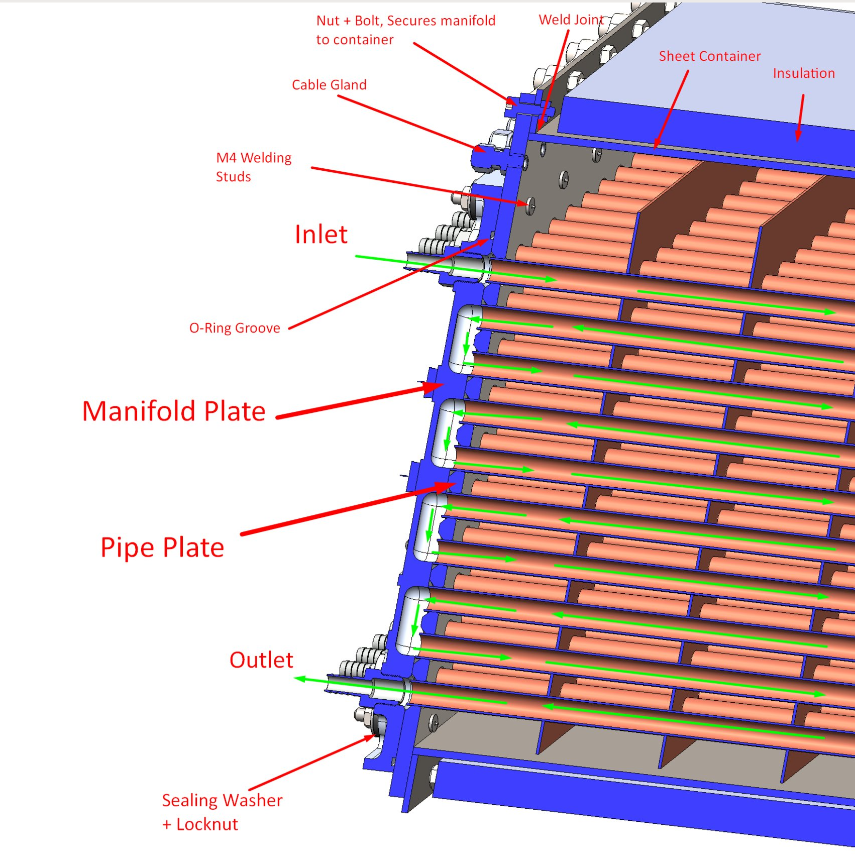
Front Manifold Assembly:
The front manifold is the largest and the most complex. The front pipe plate forms the main core of this assembly and other components are attached to this. This is bolted to the sheet metal container with use of RTV silicone gasket to seal it. Additionally, copper pipes are soldered to the holes of the front pipe plate, where 2mm chamfers are used to provide space for the solder joints. M4 welding studs are welded to this plate onto which the front manifold plate is attached onto with sealing washers and locknuts. An O-ring seal is used to seal these two plates. Due to the soldering and welding, the front pipe plate is constructed from stainless steel, meanwhile the thicker manifold plate is manufactured from aluminium for easier machineability and lower weight. Hose fittings are threaded onto the manifold plate itself and these form the inlet and outlet rows of the heat exchanger.
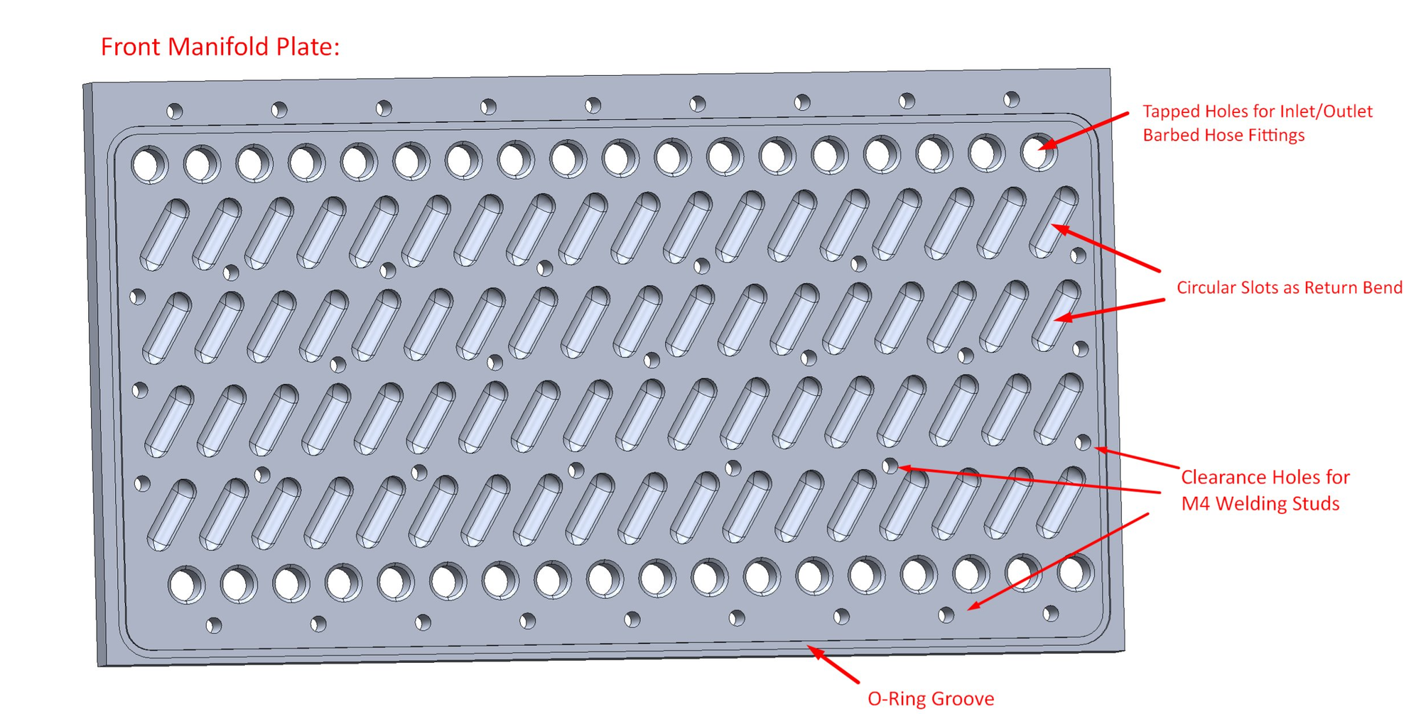
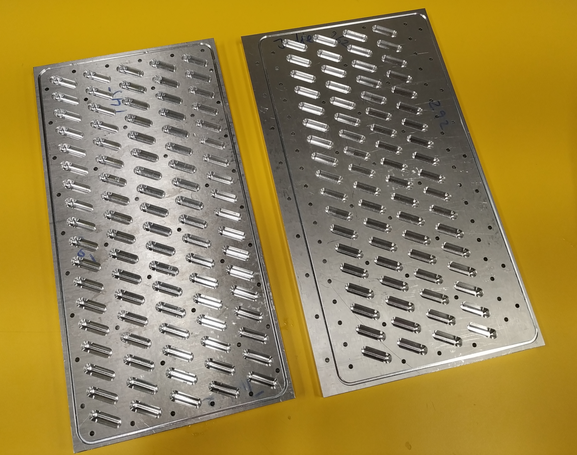
As shown by the diagram below, slots are added to the manifold plate to allow the flow to change direction.
Below is the front manifold plate itself, revealing the slots. Due to the complexity of the design, this has to be CNC milled.
Rear Manifold Assembly:
The rear manifold assembly mirrors the design of the front manifold but smaller and reduced complexity. It is also fully submerged in the PCM material. Additionally, the rear manifold rests of the support plate which is apart of the sheet container construction.
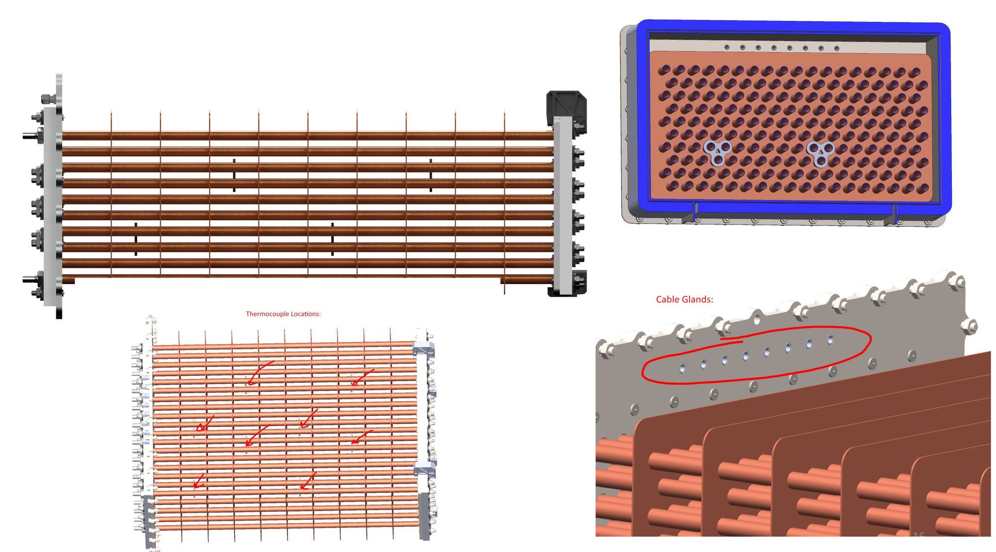
Thermocouple Mounting:
Thermocouples slide through the centre hole of the mount which feature 3 larger holes to allow it to slide down the copper pipes. The below images show the placement of these thermocouples, which will be used to measure the state of charge throughout PCM volume. Cable glands are fitted into the front pipe plate to allow cables to pass through the container.
Fully assembled design with insulation attached:
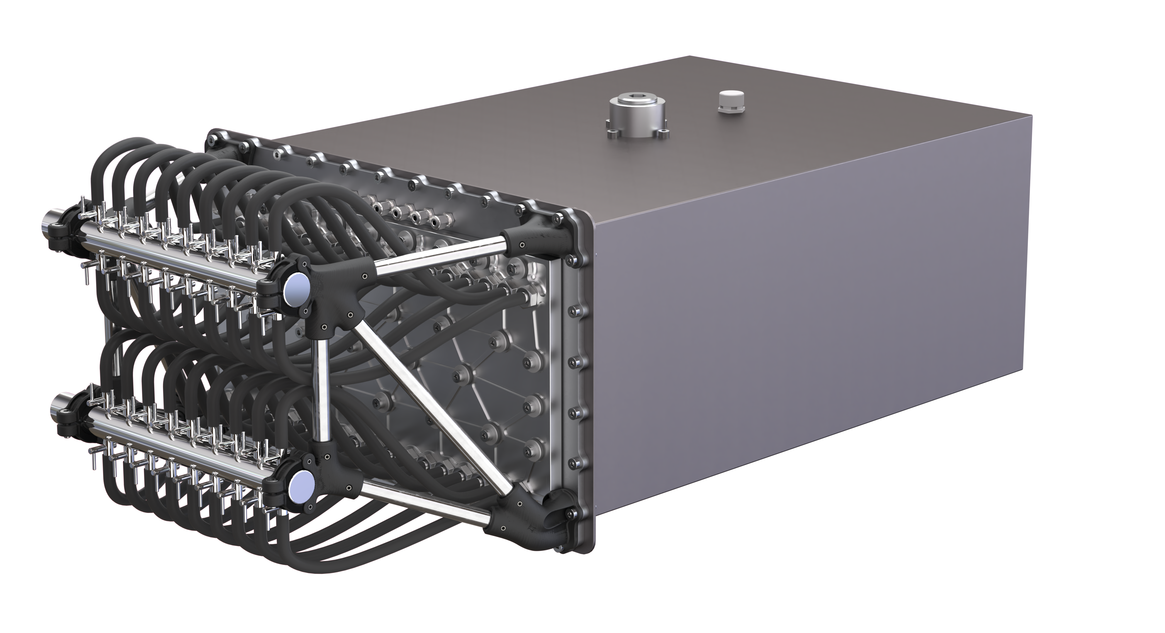
With insulation removed:
With container removed, showing the PCM wax inside:
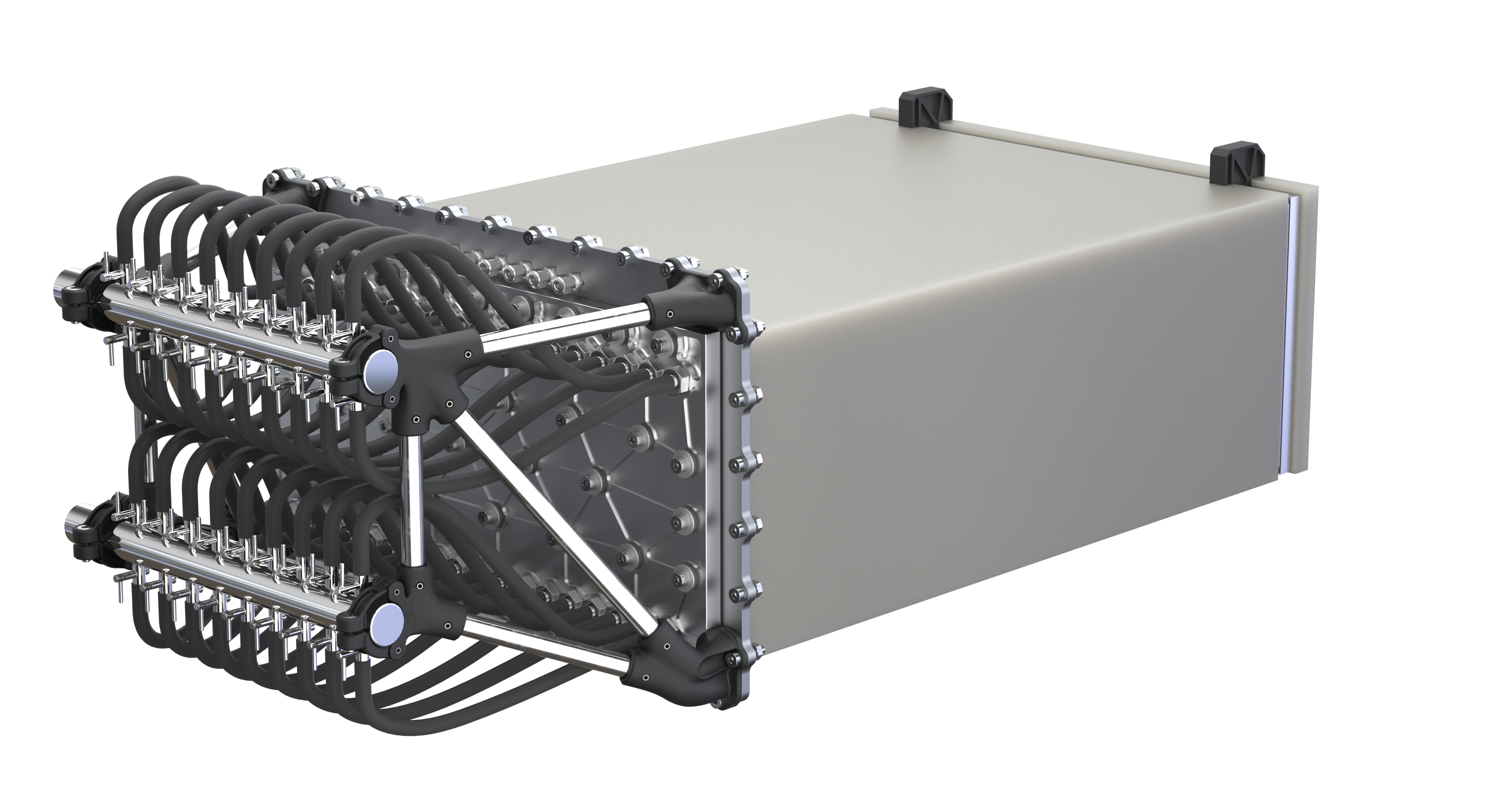
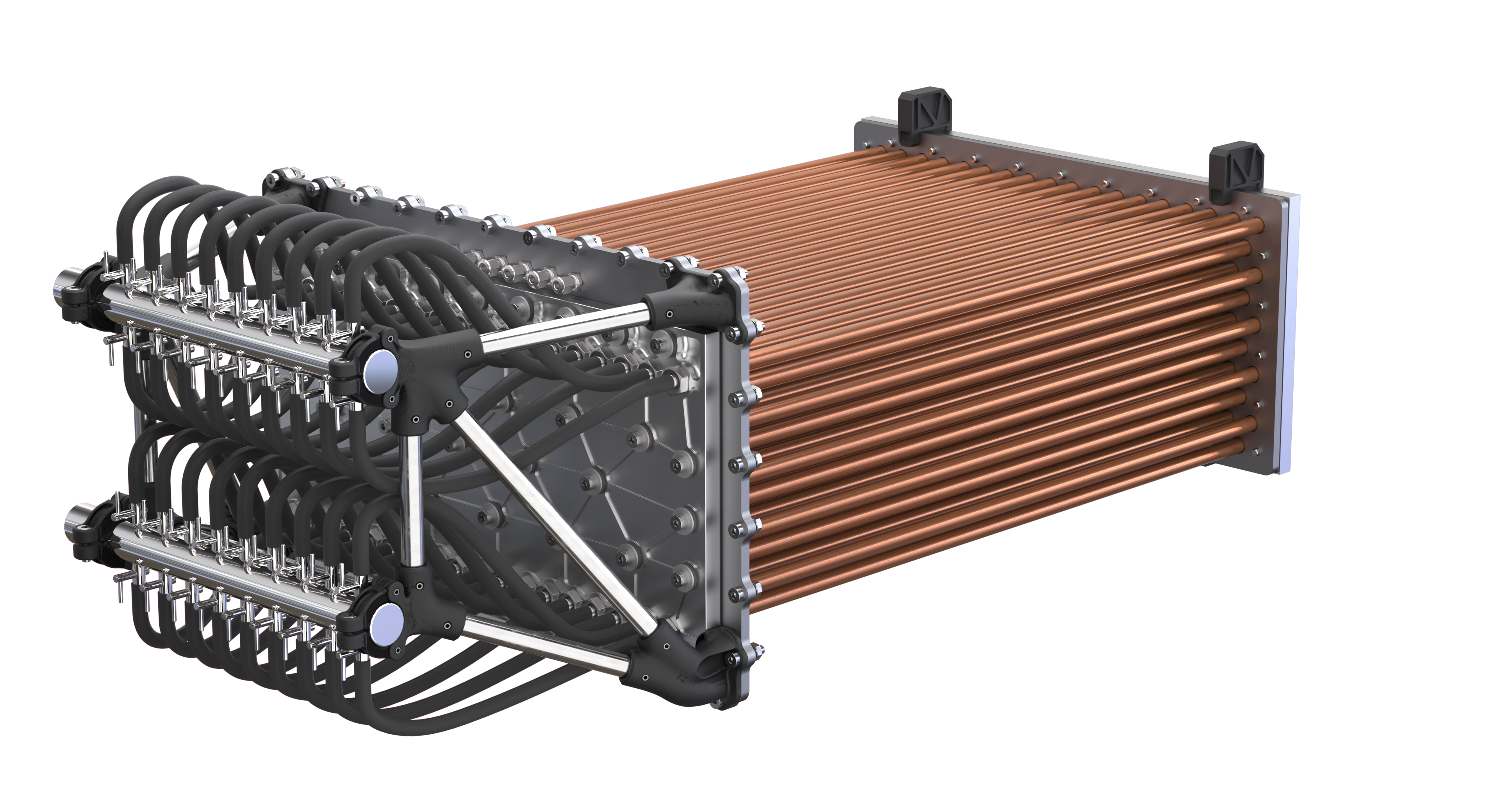
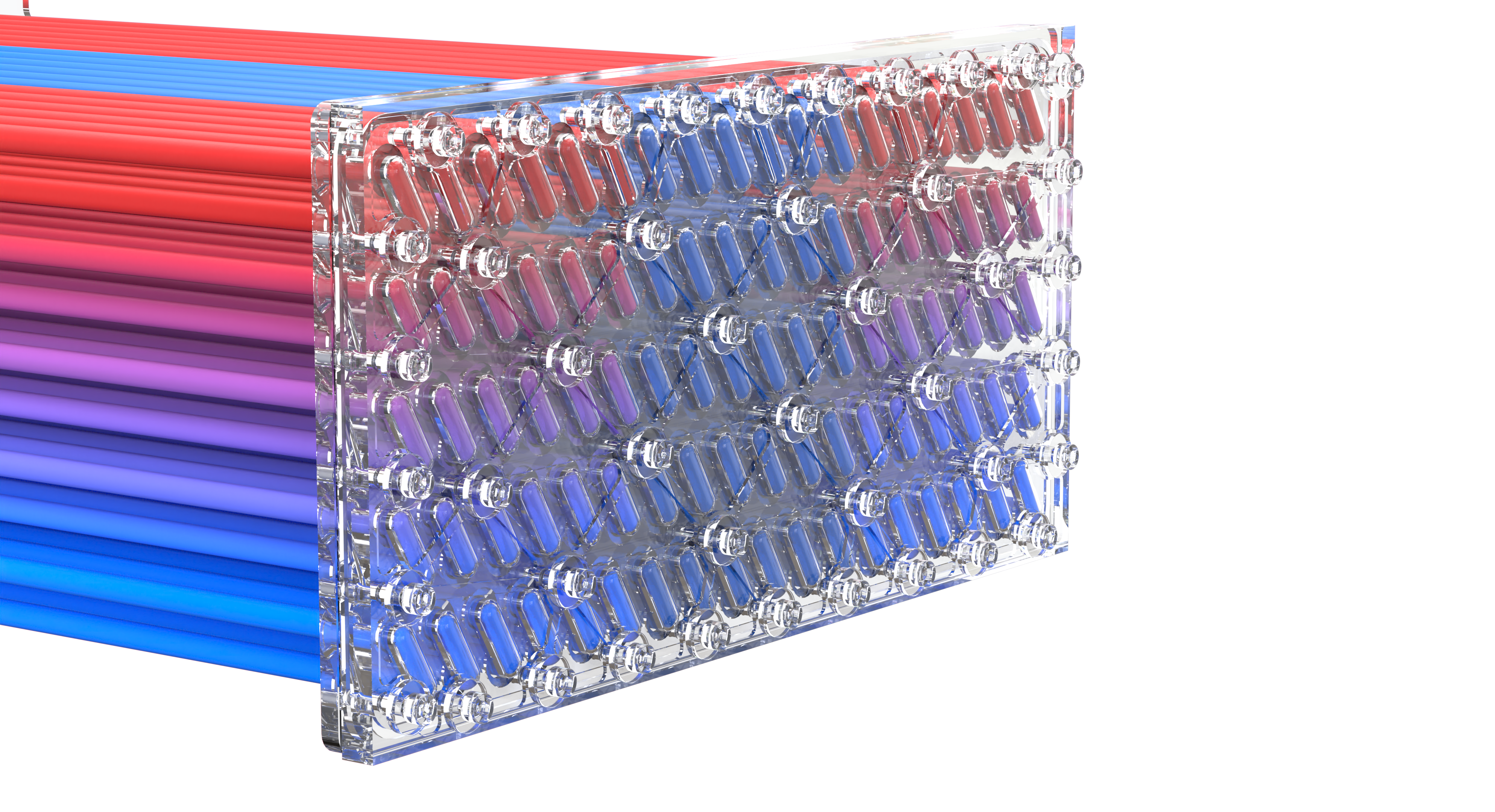
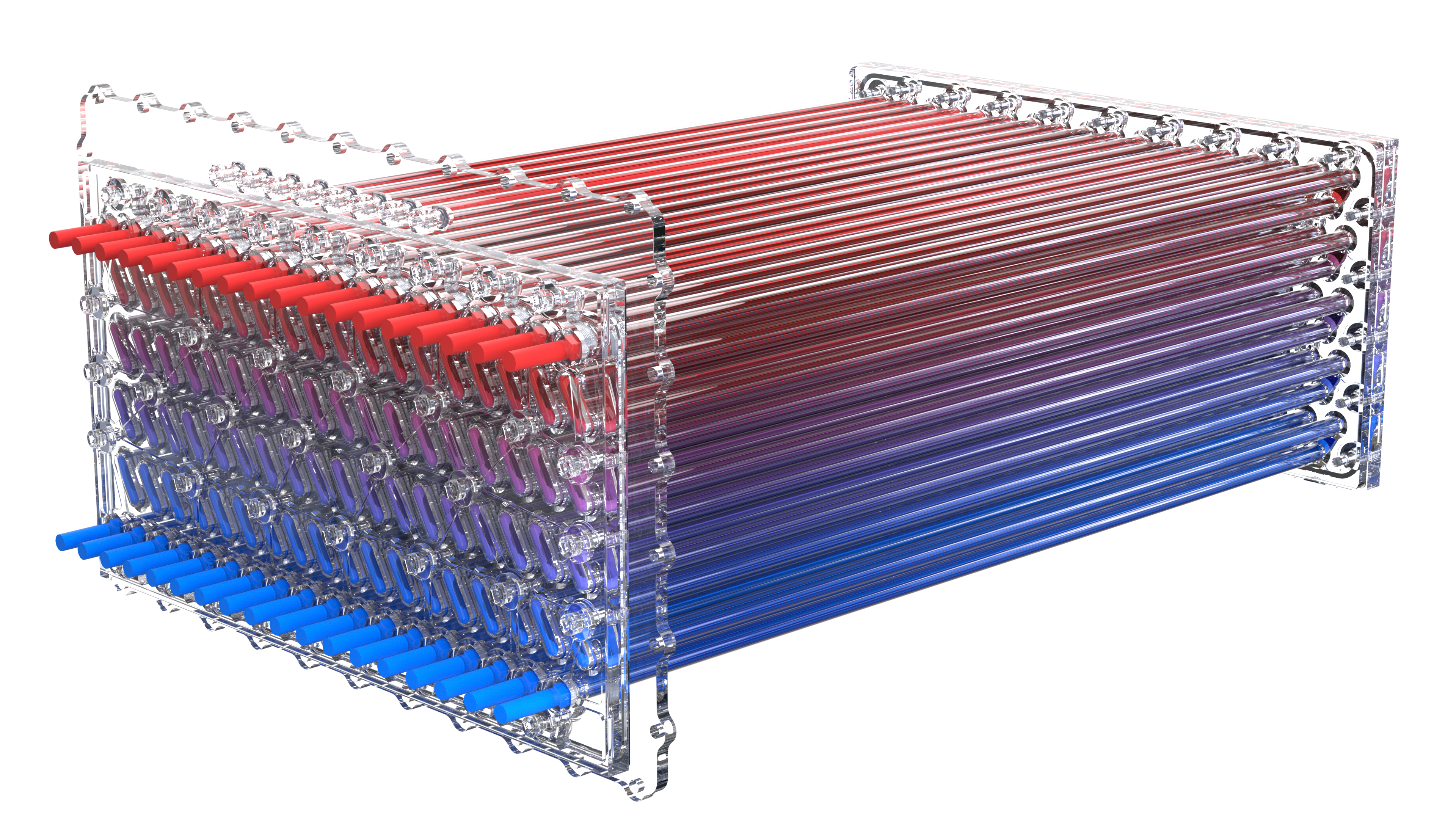
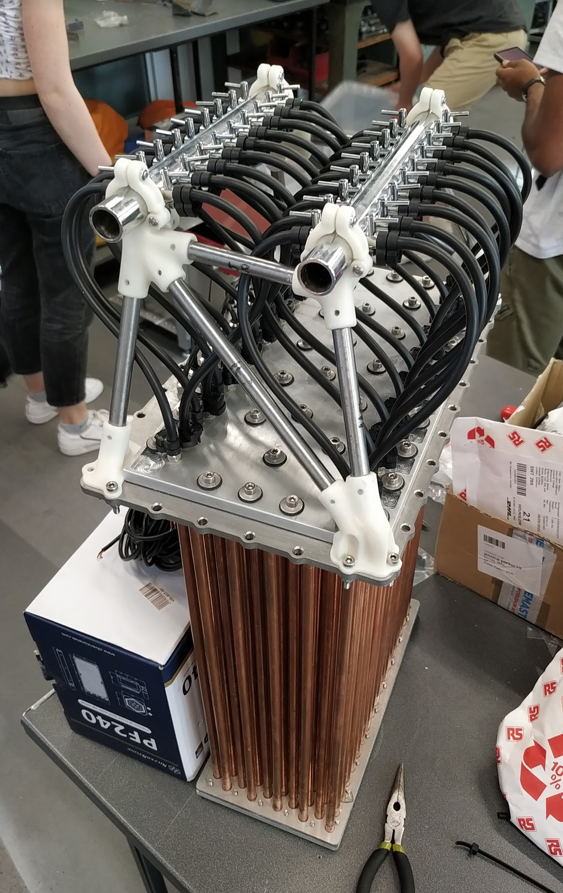
With the PCM wax removed, revealing the heat exchanger assembly:
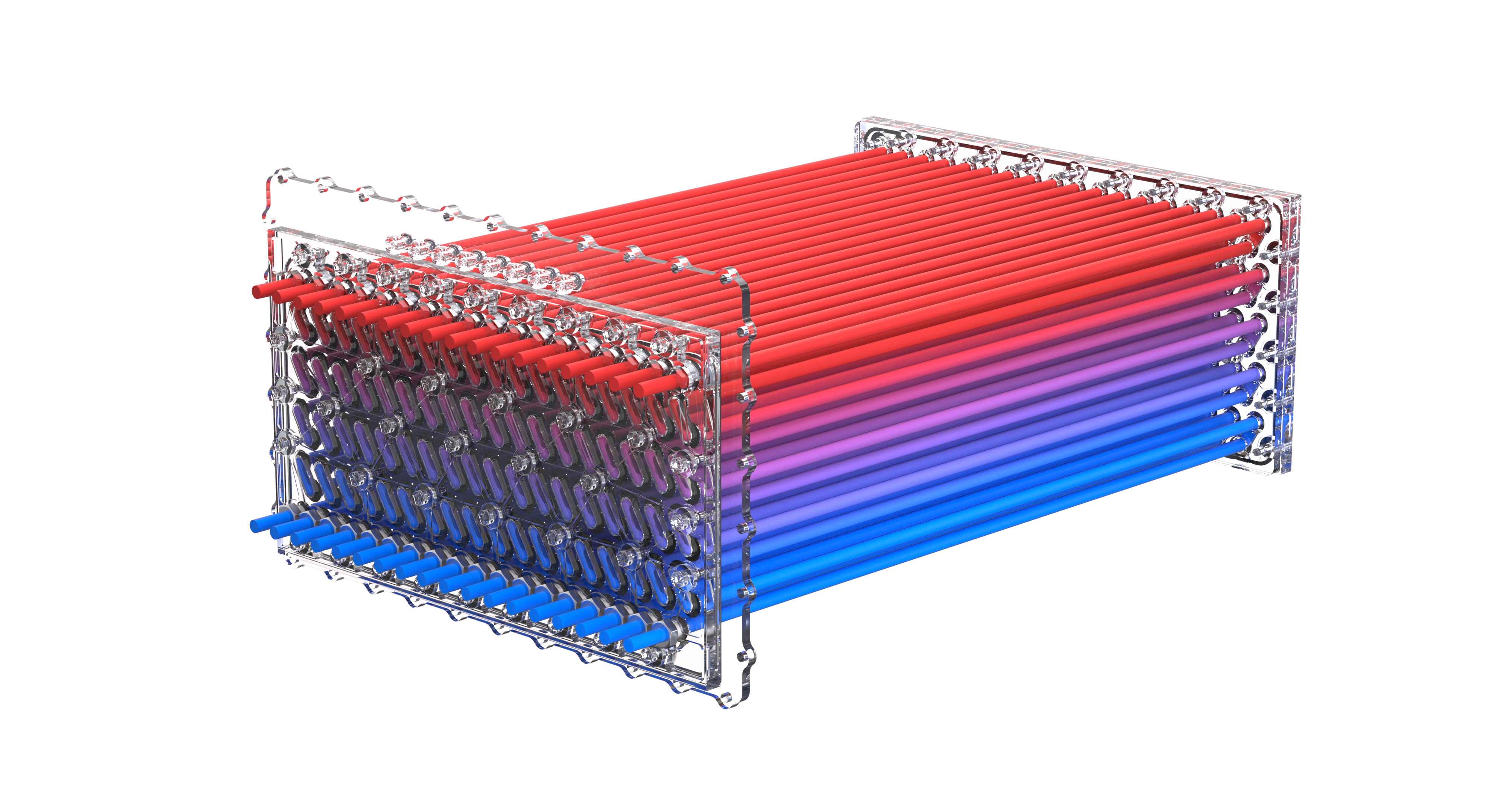
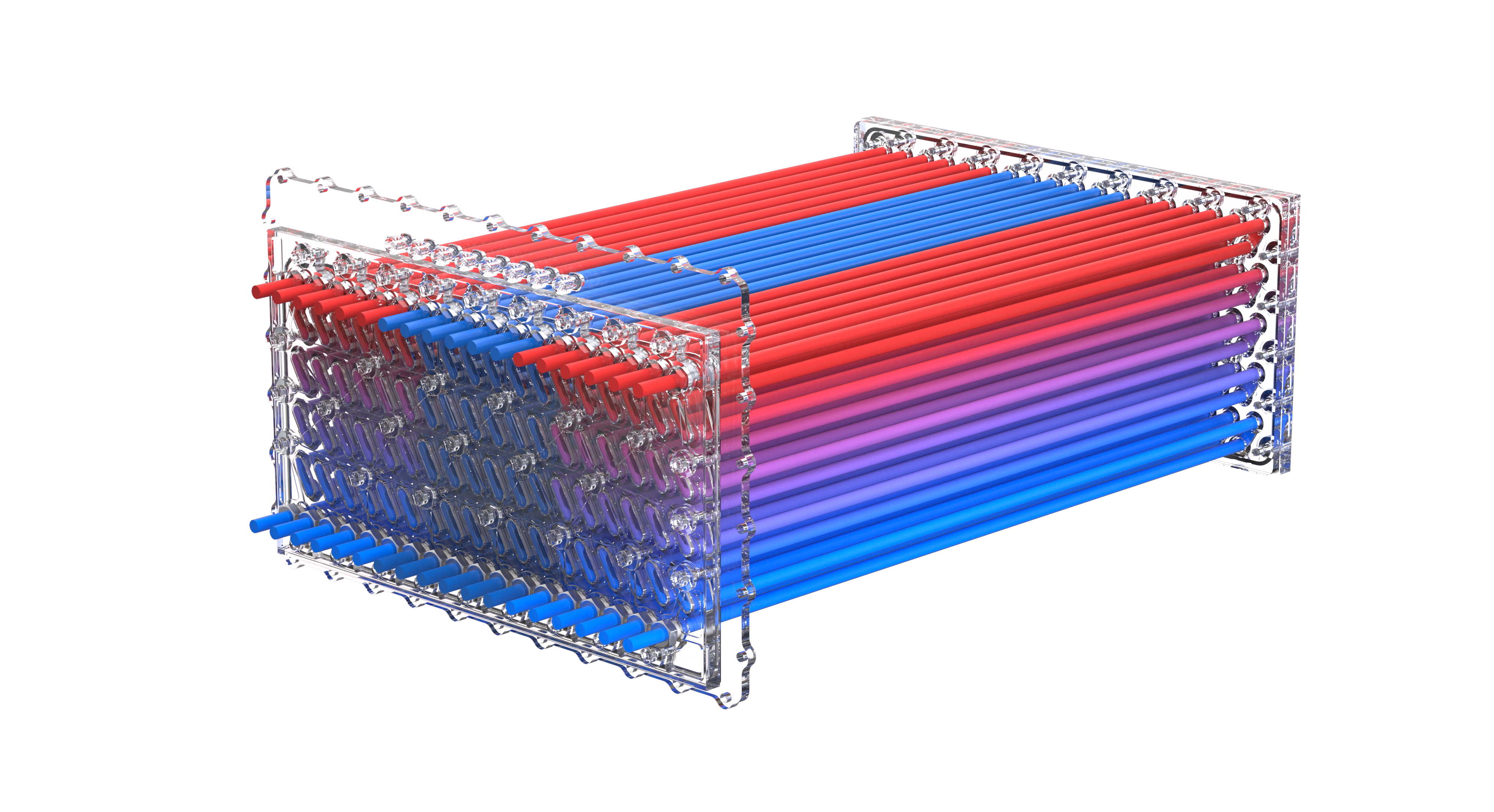
Fluid flow path. Hot engine coolant enters the system at the top row and exits at the bottom.
Each individual valve has an inlet. One could close off valves to the central region. The benefits of this may result in better temperature distribution throughout the volume.
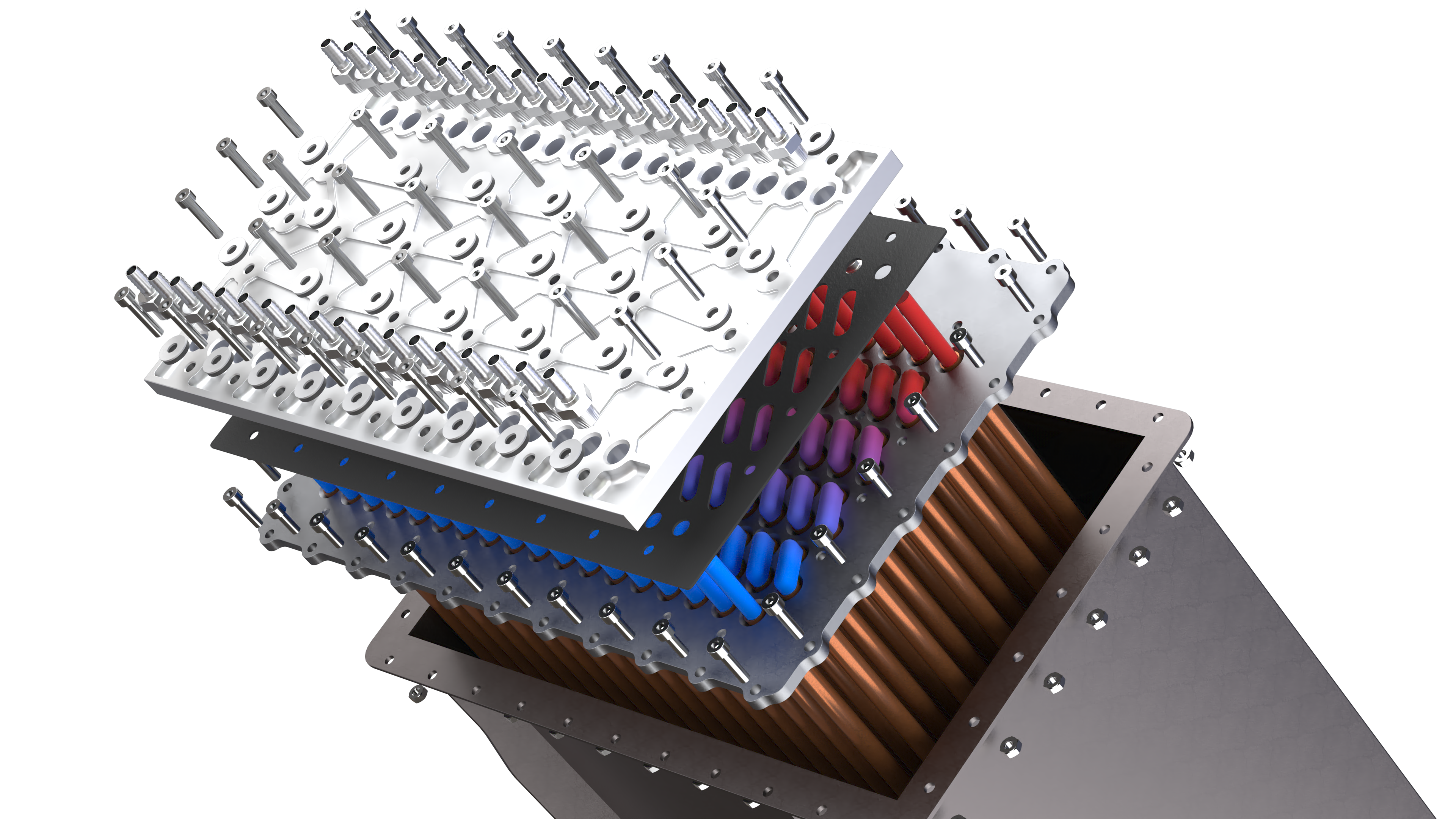
The exploded assembly of the front manifold.
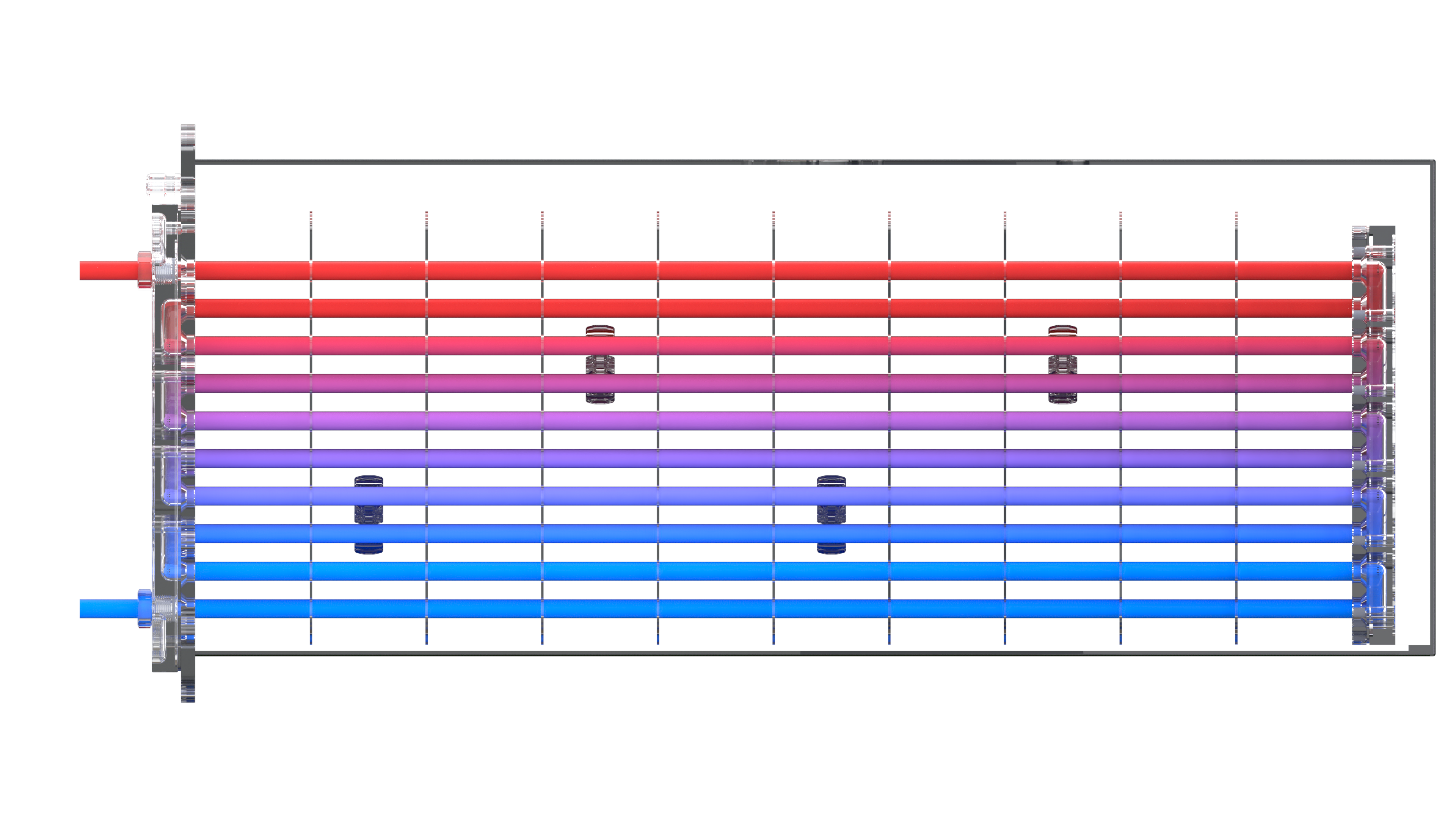
Side view. This reveals the locations of the mounts for the thermocouples (used for the state of charge sensing system). Additionally, you can see how the fluid "bends" through the manifold assemblies.
Manufacturing:
In progress
Manifold Plates:
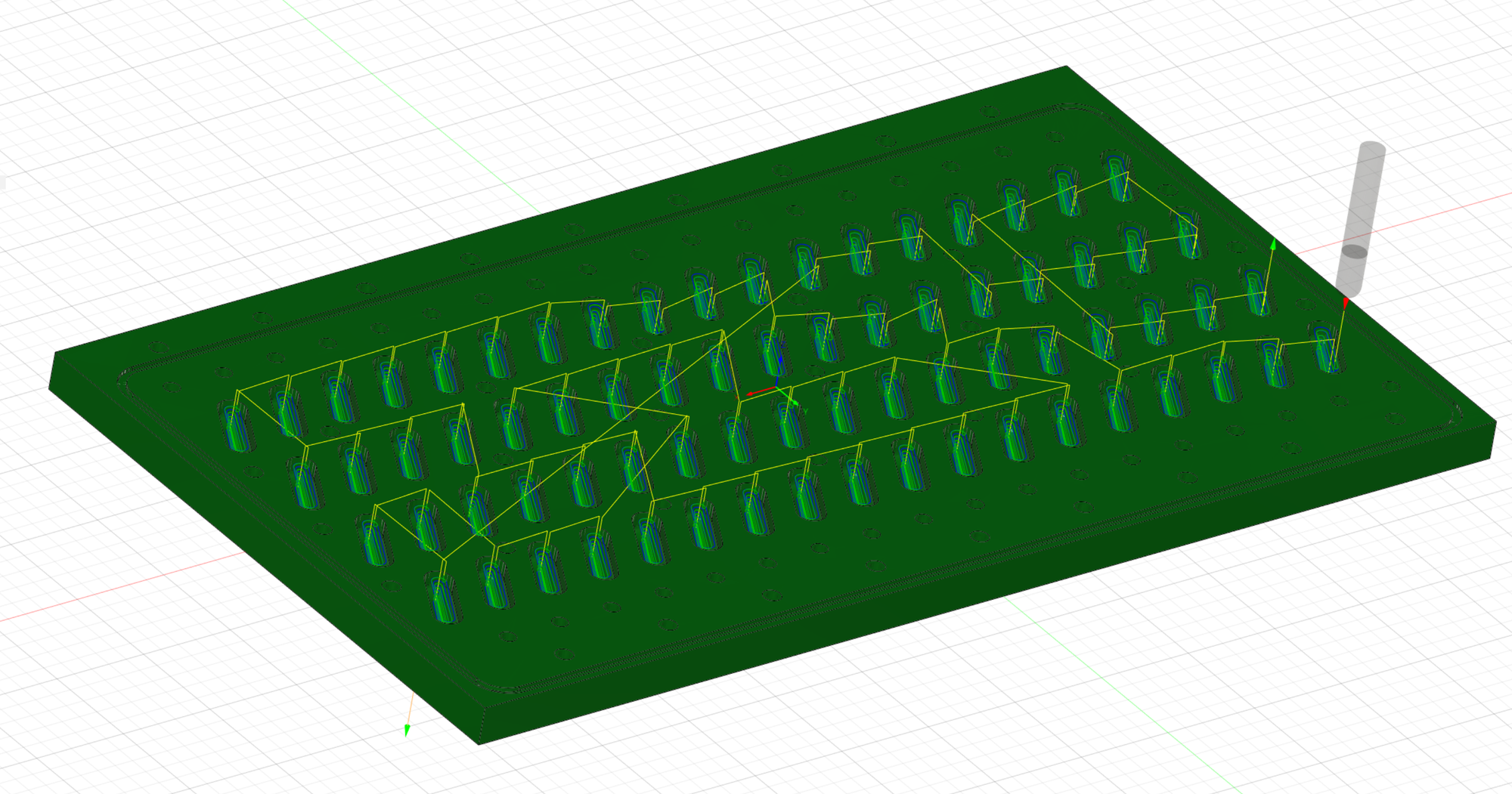
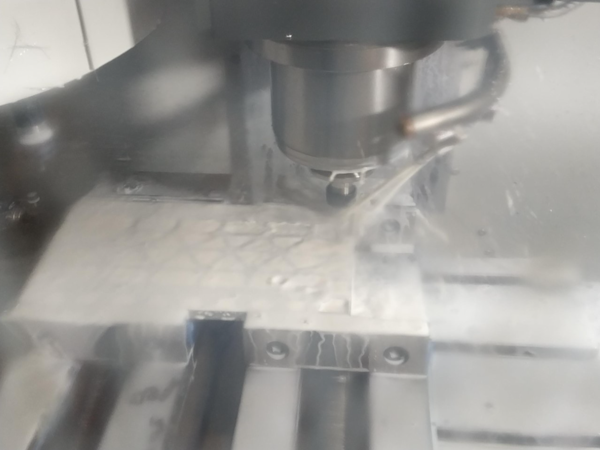
The tool-pathing was completed in Fusion360 and then approved by a technician. To save cost, a sacrificial plate to go underneath the workpiece was omitted and instead all through-holes were exchanged for small marker holes to later be drilled to size on a pillar drill. With aid from an experienced technician, each plate was milled down to size on a manual mill, then the features milled out on a Haas CNC mill.
CNC Milling:

Pipe Plates:


Laser cut and waterjet cut pipe plates manufactured from stainless steel.
Assembly:
Throughout the entire manufacturing process, the manifold plate assemblies were frequently test-assembled to examine fit. However, the key part of the assembly that ties everything together is the epoxying of the copper pipes to the pipe plates. Originally this was intended to be brazed together, but due to concerns of the exceedingly high temperature required for brazing copper to stainless steel, this idea was scrapped. We went ahead with the backup idea of making use of high temperature epoxy resin. We lasercut and constructed a plywood jig to set the positioning of the pipe plates. The plan was to construct plasticine walls and pour the epoxy for one plate, then flip and do the same for the other side. However, the mixed epoxy resin was found to be too viscious and instead we had to paste it on.
The assembly of the pipes was successful, resulting in an extremely stiff structure. Nevertheless, there was an abundance of excess epoxy resin. To deal with this, the pipe plates were sanded flush and the epoxy in pipe and threaded holes were drilled out. The big question was now whether the entire system was watertight.

Upon testing, we found that there was a significant number of leaks. But fortunately, these came from the hose fittings and sealing washers. To resolve this issue, we switched out the jubilee clips on the hose fittings for nylon clips - far superior clips. And we also applied Loctite between the sealing washer and the screw as well as simply tightening the screws harder. This seemed to resolve the issues.
Now that it was confirmed that the heat exchanger itself was performing well and sealed properly, it was time to bring the heat exchanger, splitter support structure and container assemblies together.

Above shows the fully assembled system, setup with a test rig.