Exo-Skeletal Turbojet Engine

This whole project stalked from an idea from the Dyson bladeless fan project that I was doing; Dyson used the ring-shaped fan head to induce the air using the aerofoil shape. If you took this same idea and put it onto a turbojet, you would get fast flowing air going through the center of the engine and if the center was shaped similar to an aerofoil, this flow could be sped up. The cold air from this would go through to be part of the exhaust where it would also be induced by the faster, expanding hot air but increase the overall thrust of the engine. Benefits include:
- Greater thrust
- Greater efficiency
- Reduced weight due to hollow core
- Possibility of using the center as a ramjet/scramjet to get to faster speeds
- Reduced thermal signature (mixing of hot air and cool air)
- Reduced noise
NASA had researched into the possibility of such an engine around 2000, looking into a turbofan for passenger jets. However, this required a complex bearing system including very larger diameter bearings since they were placed onto the outer circumference. These were heavy and did perform well enough for the job, leading due the project being dropped.
BUT, my idea is to put the bearings onto the inner diameter - just around the bore, greatly reducing bearing diameter, making it more feasible. Instead of doing it for a turbofan which has many complexities, I decided making a turbojet would be more viable. However, placing the bearings in the inner diameter, meant that all of the weight of the rotor would be placed onto the inner ring which would need to be supported by the outer shell through supports that could only be placed at the opposite ends after the rotor. This makes the whole structure weaker and would require stronger, heavier parts. But before, I started designing and modelling, I first spent a long time researching into all areas on how a jet engine works, looking at how the axial compressor works, how air flows through the combustion chamber
My Design:
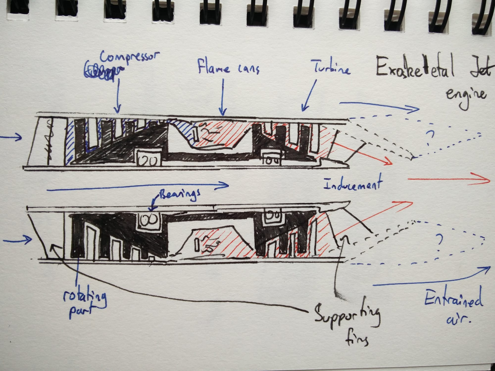
I started by sketching out some of my ideas so that it would be easier to design the model from. I came up with this idea as shown below, giving a very basic layout of the engine.
Next I went into Solidworks to make a preliminary model - just to get a better idea of sizing, shape and etc. Note that the engine will be around 160mm in diameter and about 450mm in length.
 This helped me get a better idea of how the engine would look but also some of the measurements and what kind of gaps and distances would be involved. However, it also allowed me to explore some new ideas such as the recurve shape in the inner bore. This was loosely based on an aerofoil where the curved shape extended the distance that air has to travel, making the air speed up. But the reason why I didn't go for a normal aerofoil was because the tightest point would've been close to the inlet - whilst not a bad thing, it means that after the tight(er) inlet, the air would only slow down due the widening of the passageway, due to Bernoulli's principle.
I found that the recurve shape allows for the initial increase of air velocity, increase in air velocity due to the longer distance by the curve, but also another increase in air velocity at the outlet of the bore (due to the narrowing of the channel), feeding fast air into the exhaust, increasing thrust further.
Another addition I made was the exhaust mixer - this mixes the hot and cold air, reducing noise, thermal signature and improving thrust; I would be using a forced exhaust mixer which has its unique curly shape. This engine featured a 10 stage compressor and a 3 stage turbine but I found that this many stages was not needed, not to mention that it would've caused even smaller blades which is already a concern with micro axial turbojets; I found that I rather have less stages and larger blades instead. The main benefit of doing the preliminary design is that it allows me to visualize and think about the construction of the engine and how it would be assembled, which I already knew was going to be more complex and complicated.
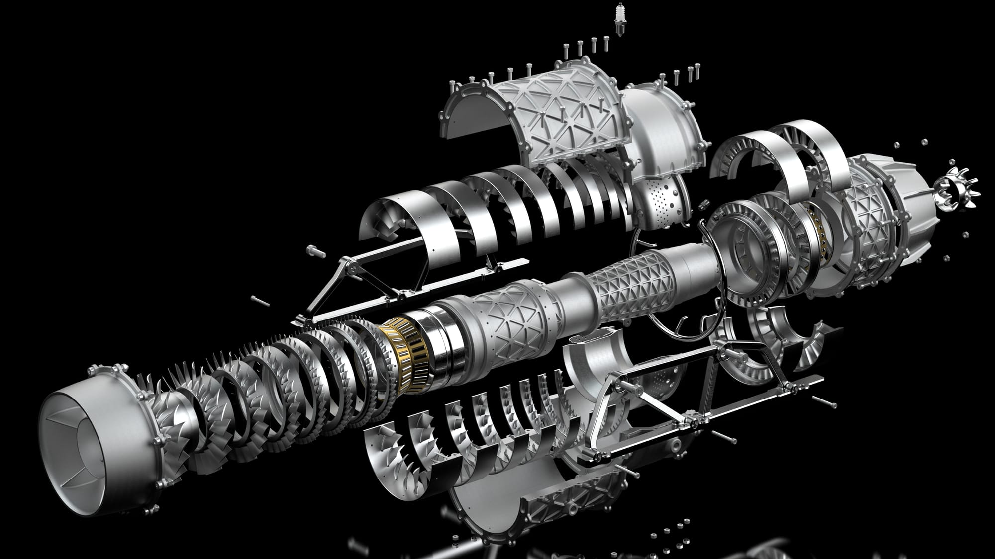
Final Design:
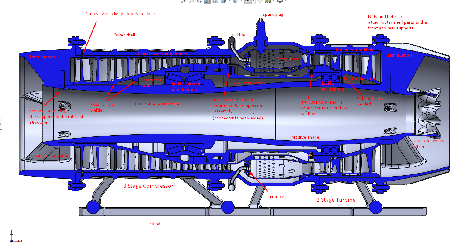
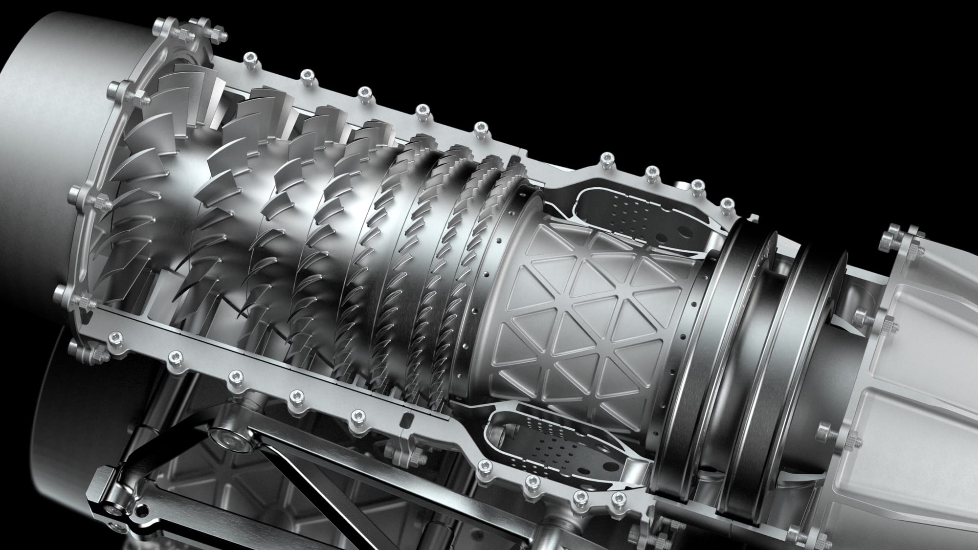
Above shows my final design of the engine, you'll notice that I've reduce the stages to an 8 stage compressor and a 2 stage turbine; whilst this seems like a loss from the original amount of stages, many similar microjets that have an axial compressor, typically use up to 5 - those attempts using less stages have often failed, with the jet unable to get to a self-sustaining state. 8 stages is a lot compared the existing working jets, but the addition of more stages will allow for higher compression ratios which will improve the performance of the engine. Due to working on a such a small scale and having a hollow drum rotor, trying to think of ways of attaching the blisks and stator blisks together became a challenging task and there was no way of using screws and bolts since there was simply not enough room. Sadly in the end the compressor rotor section would have to be welded together and likewise for the turbines. The two welded sections could then be connected by the rotor connector using grubscrews to keep it securely attached. Due to the thread, it would become extremely difficult for any screw to become loose by the spinning (note that the connector is not welded any way or form to other pieces). The stator blisks would be split in half so that they can be attached the model in halves; the top half of blades would all be welded together and the same for the lower half. Due to how they fit into the bodywork means that they will not have issues with sliding and coming loose - grub screws are only there to keep the stators stationary, stopping them from spinning axially; the turbine section locks into the body work using a kind of cross lap joint. Honestly, I am not happy with the idea of welding blicks together as it prevents the replacement of damaged blades.
I've also tried to make the blades more efficient with the blades changing in the angle of attack along the length of each blade. The turbine blades were done the best featuring the correct shape with the profile especially on how the front of the aerofoil is thick at the base but gets progressively thinner.

I've used two bearings with one for the compressor and another for the turbine. Due to the larger space available, I opted for a double tapered roller bearing which would provide superior support of axial and radial load and by using a double bearing is essential with tapered bearings so that it the outer ring wouldn't simply slip off the inner ring. The turbine section, however, had less room so instead I decided on a double ball bearing where it'll support radial load but also a little axial load due to the grooves - the balls also have less resistance than rollers. The bearings only need to slide onto their mounting position and further fastening is not needed. If you look at the the rotor is assembled, once constructed, there is no way of the bearings/rotor of being able to slide out position. The bearings are definitely larger than what they would be for a regular turbojet due to the bore size; but in this case they haven't been absurdly enlarged to the likes of a slewing ring like those that are normally proposed for ESE engines.
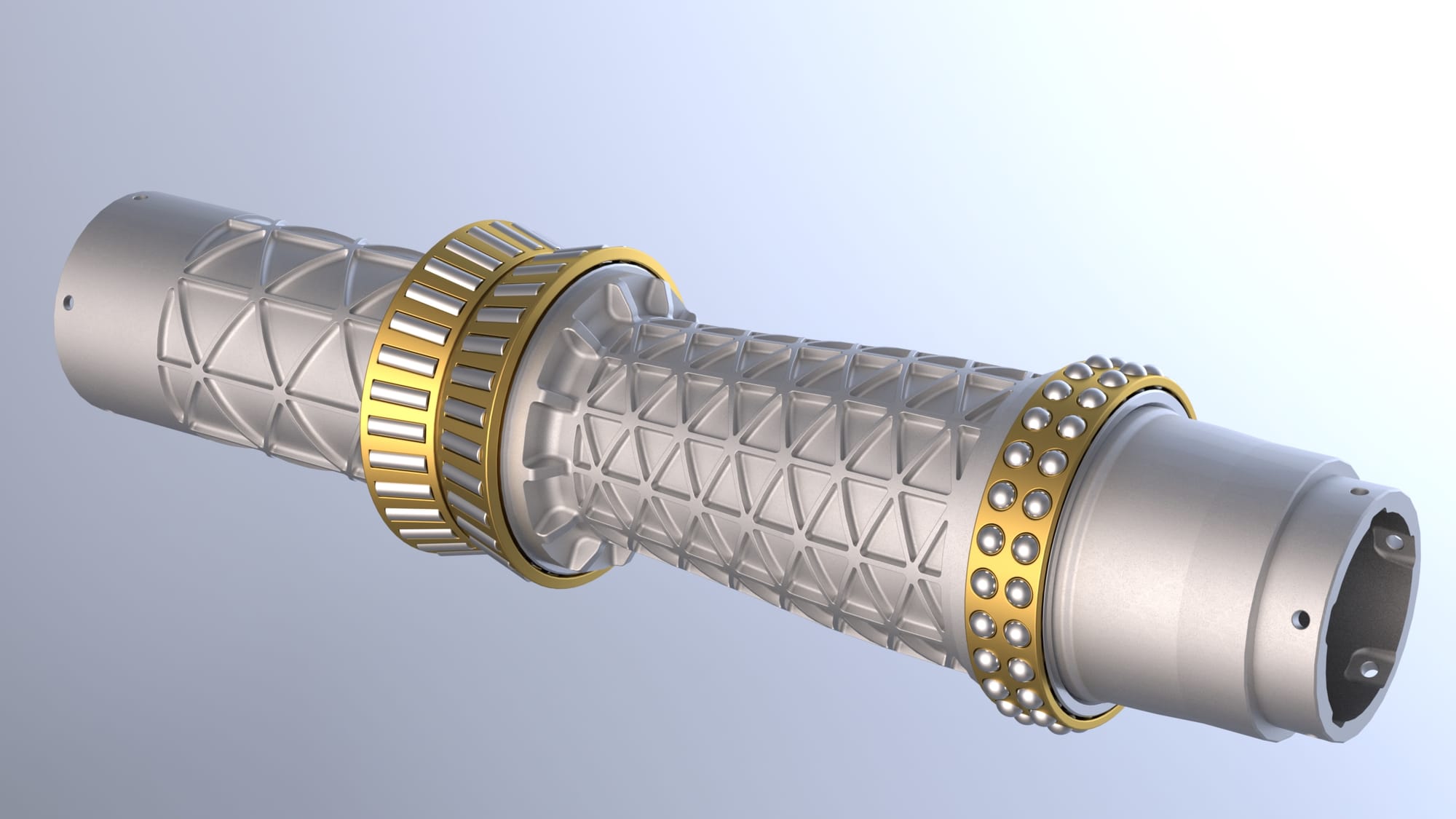
Inner structure with bearings (outer rings hidden in this render)
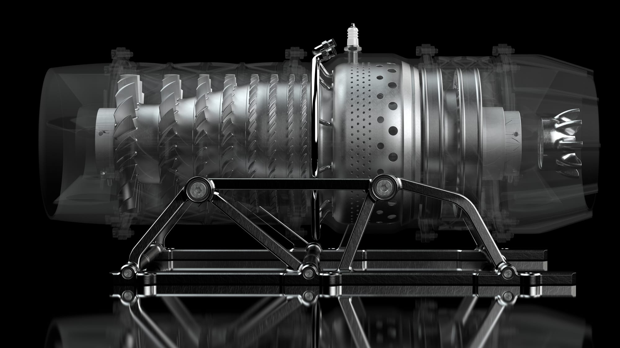
You may notice that I've used this triangulated reinforcement design around cylinders; this is because it is the best way of reinforcing a holler cylinder and is used in military jet engine outer shells and the bodywork of aerospace rockets due to the high strength-to-weight ratio that this type of reinforcement causes, only issue is that it greatly complicates the manufacturing process, requiring lengthy CNC machining to create the pattern. I used it because it allowed my load-bearing components to have greater strength but also reduces weight - plus it pushed my CAD skills and makes my project appear more complex. Creating this type of reinforcement for the image above where it has the compound curve was easily the most difficult one due to complete, having to use swirling surface planes, intersection lines and etc; but the worst bit was having to select each edge individually due to the auto-selection options not giving the correct results.

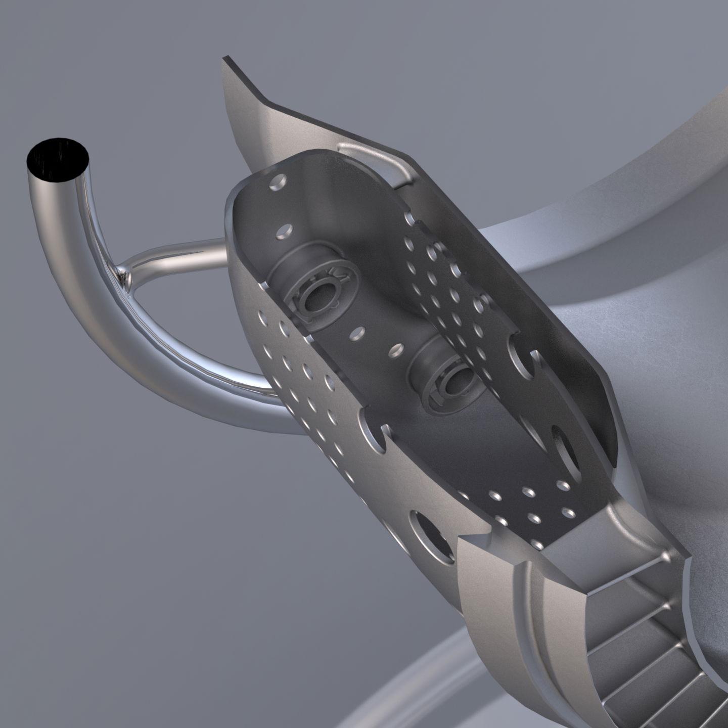
The combustion chamber was easily the worst area of the whole device since I rushed through it quickly due to having a deadline (had to be completed before going on holiday so renders could be done in batch whilst I was away). Due to rushing it, the assembly of it doesn't make a whole lot of sense, particularly the fuel line, and how it's constructed is far from optimal. The combustion chamber was meant to be a 3D-printed piece in inconel (already possible with DMLS) and this chamber would be split in two halves. What would be preventing these two halves from spinning around and moving, would be the fuel line that attaches into it. The pipes fits into its hole in the flame holder which around it has a turbine-shaped air swirler. The holes on the side of the flame holder first start of small but get bigger, progressively allowing more air to enter the chamber. At the outlet, there is a stator vane integrated into the chamber body.

These exhaust mixers are becoming quite a popular component with turbofan engines, used to mix the cold air from the ducted fan and the hot air from the turbojet core. Generally, the hot air is on the inside bore and the cold out on the outside like on turbofans; but with my engine design it is the other way around and furthermore the mixer is designed to let more cold air into the hot air, which is exactly what my mixer has done. It will reduce the noise created by the engine as well as increasing the performance.
You may have noticed that the turbine blades are in fact in the incorrect direction, resulting in rotation being opposite of that of the compressor. This mistake can be amended without much difficulty by reflecting the part/sketches; however, what is a problem, is how there is a third turbine stator blisk after the last turbine rotor blisk. This was as a consequence of my assumption that the stator is placed after the rotor for the turbine like it is for the compressor. I noticed that I was mistaken after feeling that it didn't quite make sense but it was too late so I simple had to add another set of stator blades before the first turbine rotor and this had to be integrated into the combustion chamber components. Otherwise the whole turbine section could be moved right towards the outlet, especially as a lot of space was taken up by the third stator; this would have allowed for a larger combustor chamber (which I believe is smaller than preferred currently) or simply so that the length of the engine could be reduced, making it more compact and lightweight.
Weight Problem:
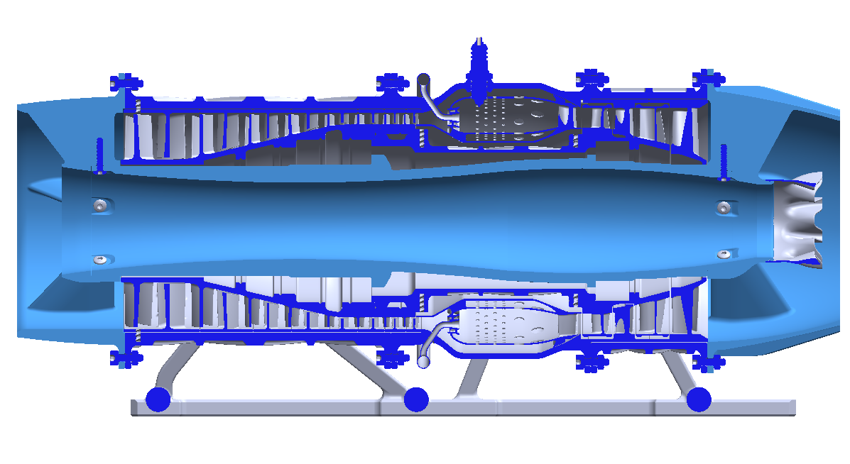
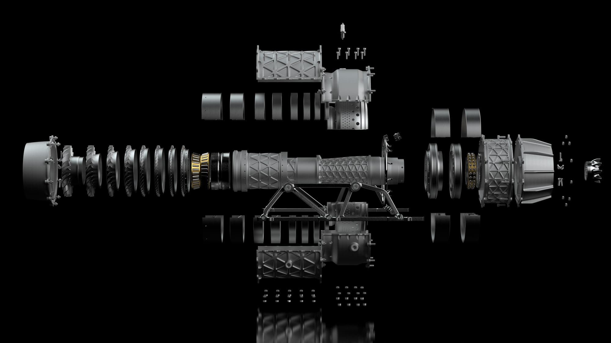
Under the light blue highlight shows the 3 main load bearing parts. The outer shell of the engine connects the front and rear supports but is quite thick so that it does not deform under load - especially as the engines mounting points are along this outer shell. Typically with most jet engines, the outer layer is very thin but this is due to the fact that it doesn't have to support the whole engine.
So to reduce weight the best way would be to attach the jet engine to the plane/similar by putting the mounting points on the front and rear supports. This will allow the the material to be thinner for the outer shell. This idea works best where the engine is integrated into the load-bearing fuselage like on a jet fighter.
Other Ideas/Potential Applications:
What I have designed, is simply a small turbojet to explore the idea of an ESE engine and such an engine could be made to prove whether it could work and be a viable design. However, this unique design opens doors to new ideas and applications that it could be used in. Here I'll just explore some ideas that I had.
Ramjet/Scramjet
As previously mentioned, the center 'tunnel' of the exo-skeletal allows the opportunity for placing a ramjet or scramjet in that empty space. This would mean that the turbojet could be used to get the plane from idle to supersonic speeds but the ramjet/scramjet can be used to boost the aircraft to greater supersonic speeds but this can be done simply rather than the complex design of previous similar aircraft engines like the Pratt & Whitney J58 turboramjet that was used in the famous Blackbird. This type of ramjet
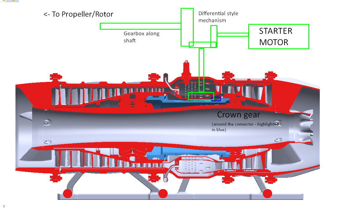
Turboprop/Turboshaft
I worry that this kind of engine may not be suitable in a large size like those used in jet fighters and similar due to the long internal bore structure which would be prone to all kind of stresses and bending/wobbling. So another use of these ESE engines is for prop or helicopters.
(excuse the rough sketch ontop)
The connector part (highlighted in blue) that connects the compressor and turbine rotors can feature a crown gear where the teeth point parallel to the engine center-line. As shown by my rough drawing, another gear would need to lock into this crown gear which leads to a differential style mechanism. The starter motor could be simply an electric motor (if the engine is small enough) or for larger engines, a starter unit like a pneumatic motor, relying on high pressure air input from either an internal APU or an external source. The reduction gear ratio simply from the gear to the crown gear will also work in the starter motor's favor. However, this makes it less ideal for power transmission to the propeller and a more extensive gearbox (preferably planetary) would be required in order to compensate. Prop turbojets are already seen as more efficient, particularly in subsonic speeds and the addition of an ESE turbojet would only increase the efficiency. The inclusion of the internal bore would also allow for quieter operation which is important with prop/helicopters since they fly at relatively low altitudes.
Due to cold air rushing through the internal bore and passing through the hot exhaust, mixing with the hot air (due to the mixer nozzle), this could possibly reduce the heat signature of a helicopter which is in the best interests for military helicopters to avoid heat-seekers.
APU:
You may have noticed that I have not included a form of APU in my design. Lacking a solid central rotor but also a way to get to the rotor from the outside has made it very difficult to attach an APU; many microjets typically use an electric motor to get the rotor up to speed or use an external pressurized air source, i.e. a leafblower to blow into the inlet to get the engine going. With my design, it's probably more effective to simply just go with the leafblower idea.
One good idea is to use the system suggested in my previous idea of having a shaft connecting with a geared rotor. Here, either a pneumatic or electric motor can be used to start up the engine.
Turbofan:
Just using a turbojet has started become more uncommon in planes unless in military jet aircraft or as turboshafts/turboprops; although turboprops generally use centrifugal compressors instead of the far more complex axial compressor - although I think it it is possible to possibly create an ESE turbojet with a centrifugal compressor. Furthermore even military jets are favoring low-bypass turbofans which improve the efficiency, reducing cost per mission but also increases the range of the aircraft. I've started with an axial turbojet because it offers a good starting point and has a simpler design compared to a turbofan which has it's own complications - particularly the multiple spool design (note that this became a sticking point for NASA). I believe that not too difficult at all to add the ducted fan to my current design in order to convert it into a turbofan but the issue is that this single-spool design is far from ideal especially as manufactures typically use up to 3 spools so that the fan and compressor can work at it's respective optimal RPMs.
If a viable exo-skeletal turbofan could be designed, I believe that this could definitely become a game-changer. I would love to tackle this challenge at a later point.
Even so, I doubt such engines would make it to large turbofans such as those used in large passenger jets mainly due to the fact that the bore size would be large, leading to very large diameter bearings and the viability of this is poor (which is one of the reasons why NASA dropped the project). It may still be better that these ESE turbofans remain with lower-diameter engines like those used in military fighter jets, private jets or similar smaller aircraft.
Cruise missiles:
Personally, I believe that this kind of engine will probably be more viable when the engine is smaller, mostly due to the fact that there is less stress on the inner structure. Due to the limited space in a cruise missile, a small turbojet is ideal - not that this is a new idea since cruise missiles specifically use a turbojet only using a rocket booster for the initial take-off to get it up to speed quickly. But, an ESE turbojet offers the benefits of possibly reducing heat signature, more efficient (increases range, or doesn't need to take as much fuel, which allows more room for other things like more explosives) and faster even due to the cool air coming through the internal bore adding to the exhaust gas velocity.
But, the addition of a ramjet/scramjet inside of the internal bore could be used to accelerate the aircraft to even faster speeds, even allowing the missile to achieve supersonic cruise or beyond (cruise missiles typically travel at sub-sonic, which makes them more vulnerable) to allow them to hit their targets quicker, with more force but more importantly so that it's harder to be hit by enemy countermeasures. Even if super/hypersonic cruise is unrealistic or not preferred (for the sake of range for example), be able to have that boost of speed on demand may be important, especially if needed to outrun missile countermeasures or similar.
Furthermore, as mentioned when I was discussing about reducing the weight of the engine, having the turbojet inside of the missile allows the chance for the turbojet to be integrated, where the supports could be attached to the main structure of the missile instead of needing a strong outer shell.
This is one application that an ESE turbojet could fulfill.
Conclusion
My design is far from perfect and there are plenty of features with flaws that need to be improved upon but it does give some insight to what a possibly viable exo-skeletal jet engine could be like. Whilst I am confident that my design will work, it's hard to say whether it'll have an advantage over a regular turbojet of the same size and I certainly doubt it would in a static test due to the inner bore's benefits come into play when there's airflow through it. There's still plenty of hurdles before this idea could be considered for actual commercial use especially with the bearings even with my idea of placing them on the inside rather than on the outer shell which may be fine for a microjet like mine but will become much more problematic with large engines. Another thing is that this project has been done without calculations nor flow simulation but this does not deter me from wanting to be able to do both of these in the future.
Nevertheless it has been a thoroughly enjoyable project and it was exciting to learn new concepts concerning both physics and the mechanical side. But above all, it was great to be pursuing something mostly new rather than copying an existing design, and coming up with my own ideas to the features and solving problems like the assembly of this device. This whole project is something I'd love to revisit in the future and try to tackle a turbofan variant, hopefully even building one in real life. In short, it was a fun experience
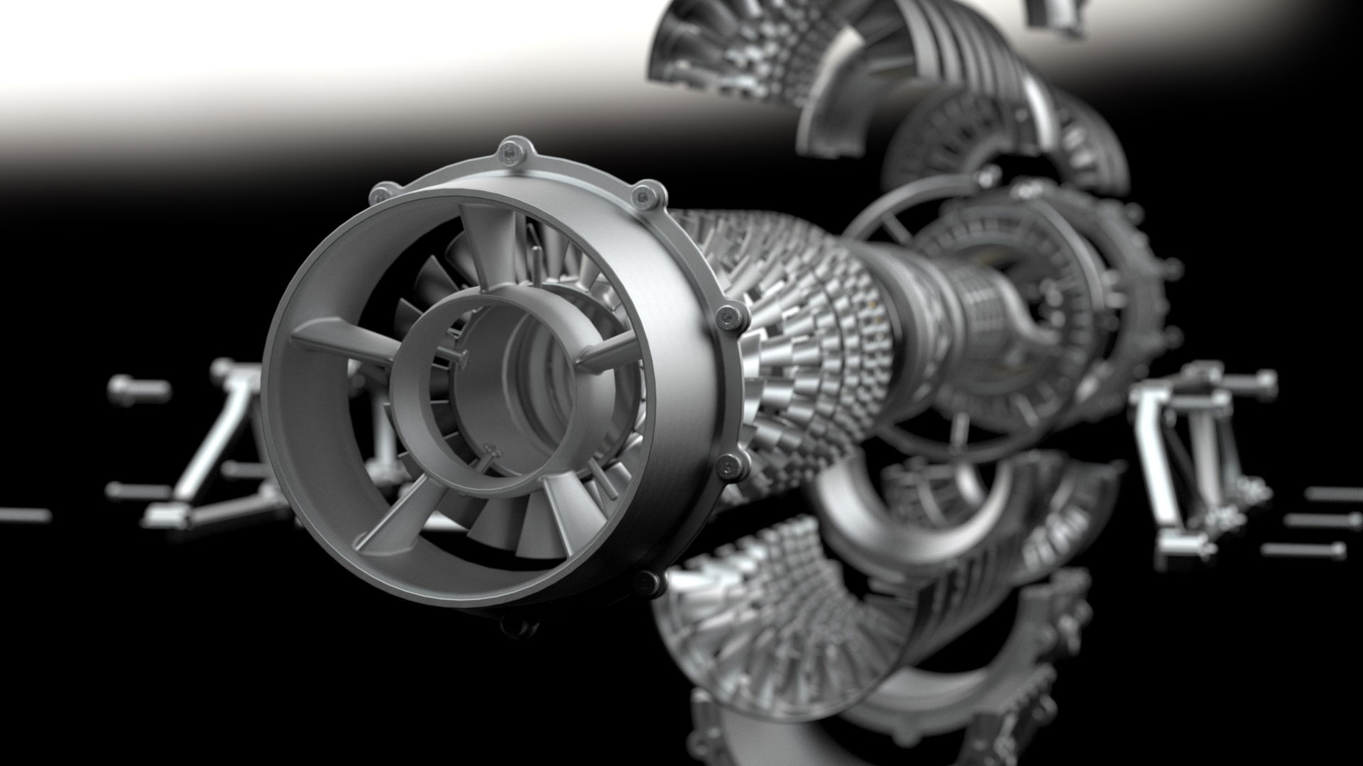
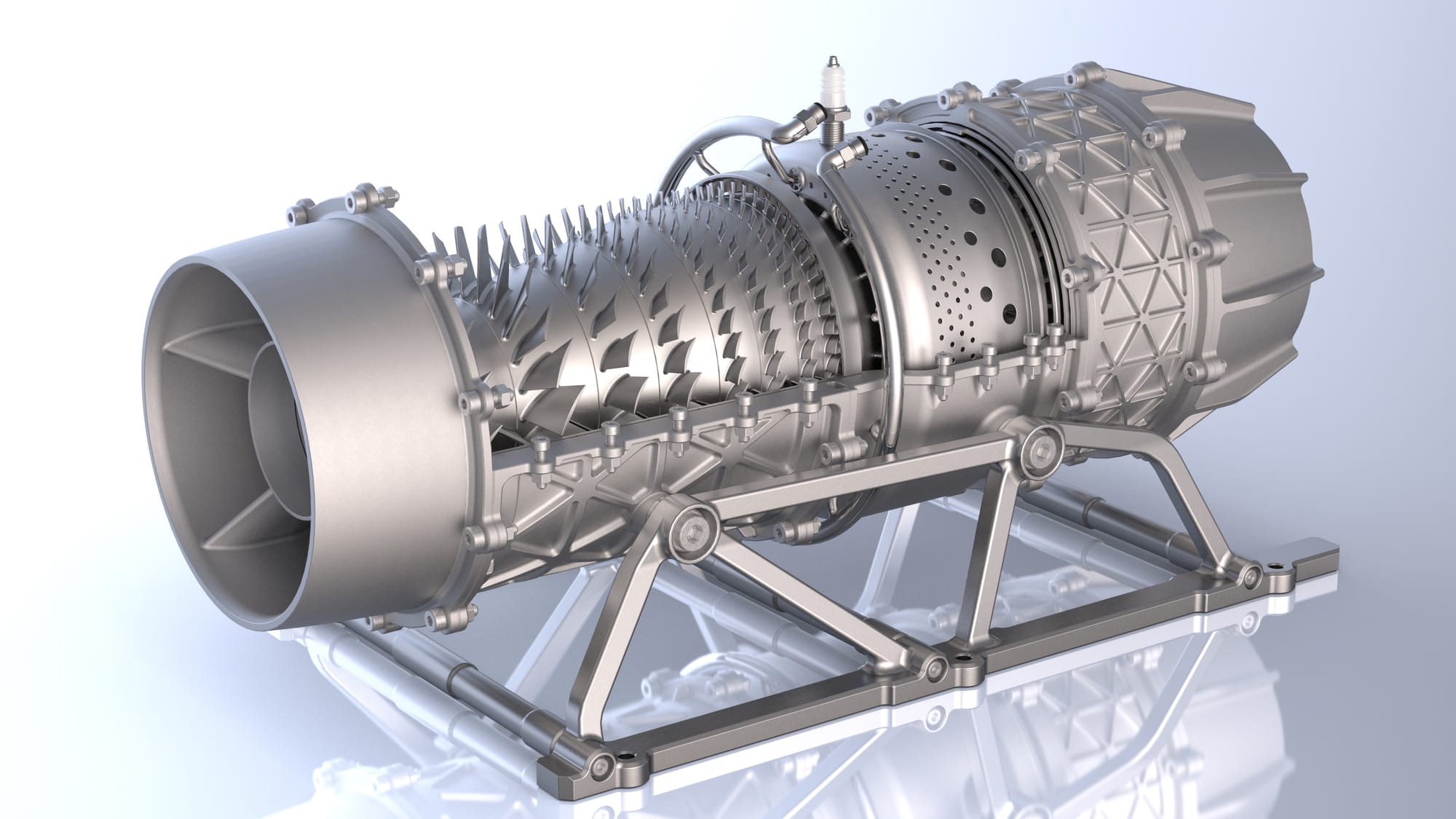
More Renders
Note that I would've loved to have done an animation showing the assembly of the engine but it was simply too much for my computer when trying to setup the animations - there are 128 bolts and nuts alone, excusing the extra 30 grub screws that I omitted from the model assembly.