Water-Cooled Hot Fluid Pump
For the ME3 DMT heat storage project, due to the unavailability of a functioning engine to conduct testing upon, we had to use a pump to provide the heat storage system with coolant flow. To more realistically simulate the engine, the pump would need to provide boiling water at a flow rate of at least 16L/min - ideally achieving up to 60L/min. However, it was challenging to source a pump that could both provide the flow rate range and high temperature fluid capability. A pump would need to be a centrifugal pump to achieve these flow rates and the high temperature requirement makes shaft sealing significantly more challenging and thus expensive. As a result, we found that a suitable pump would cost at least £330. At this time in the project, we did not have the funds to purchase such an expensive piece of equipment.
So I proposed that we attempt 3D printing the pump of our own design. This appeared feasible due to myself already being equipped with a nylon MJF printed compressor wheel and a powerful bladeless motor (~1200W power). The volute casing would be printed by nylon MJF printing, which would cost less than purchasing a pump. The key challenges in this design would be the temperature limitations of a nylon pump body and the shaft sealing.
Temperature Resistance:
To combat the high temperature of the boiling working fluid, I entertained the idea of water-cooling the pump body. Channels would be integrated into the pump body, wrapping around the pathway of the working fluid. Due to the use of MJF 3D-printing, such complex geometries would be perfectly feasible. A separate loop of coolant would be supplied to ensure that the pump body does not reach critical temperatures.
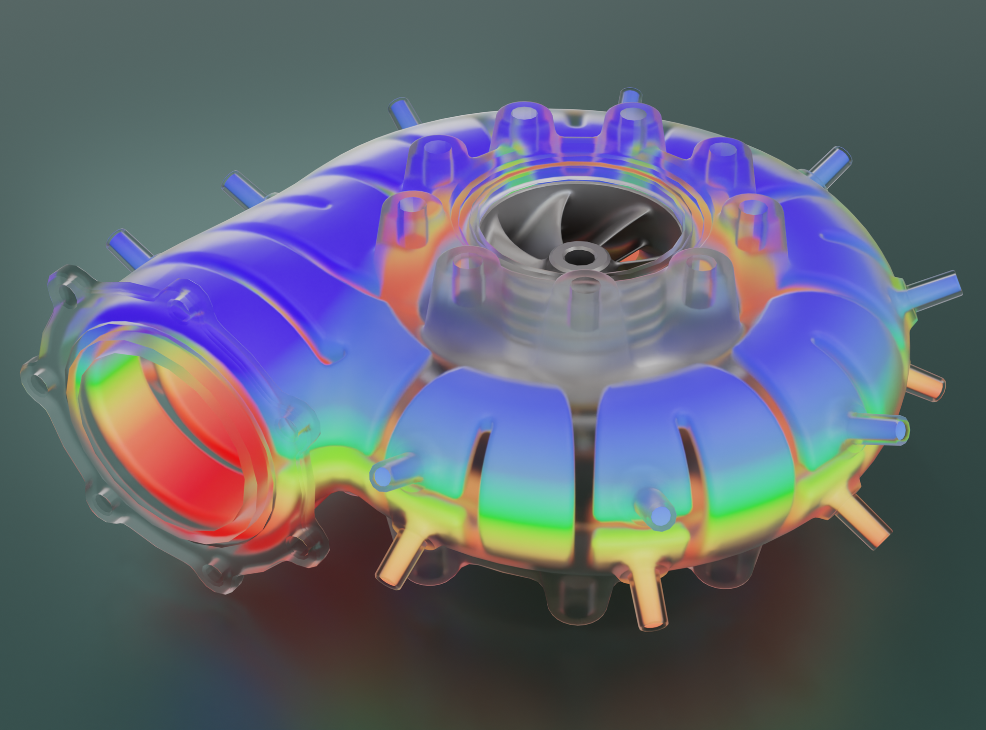
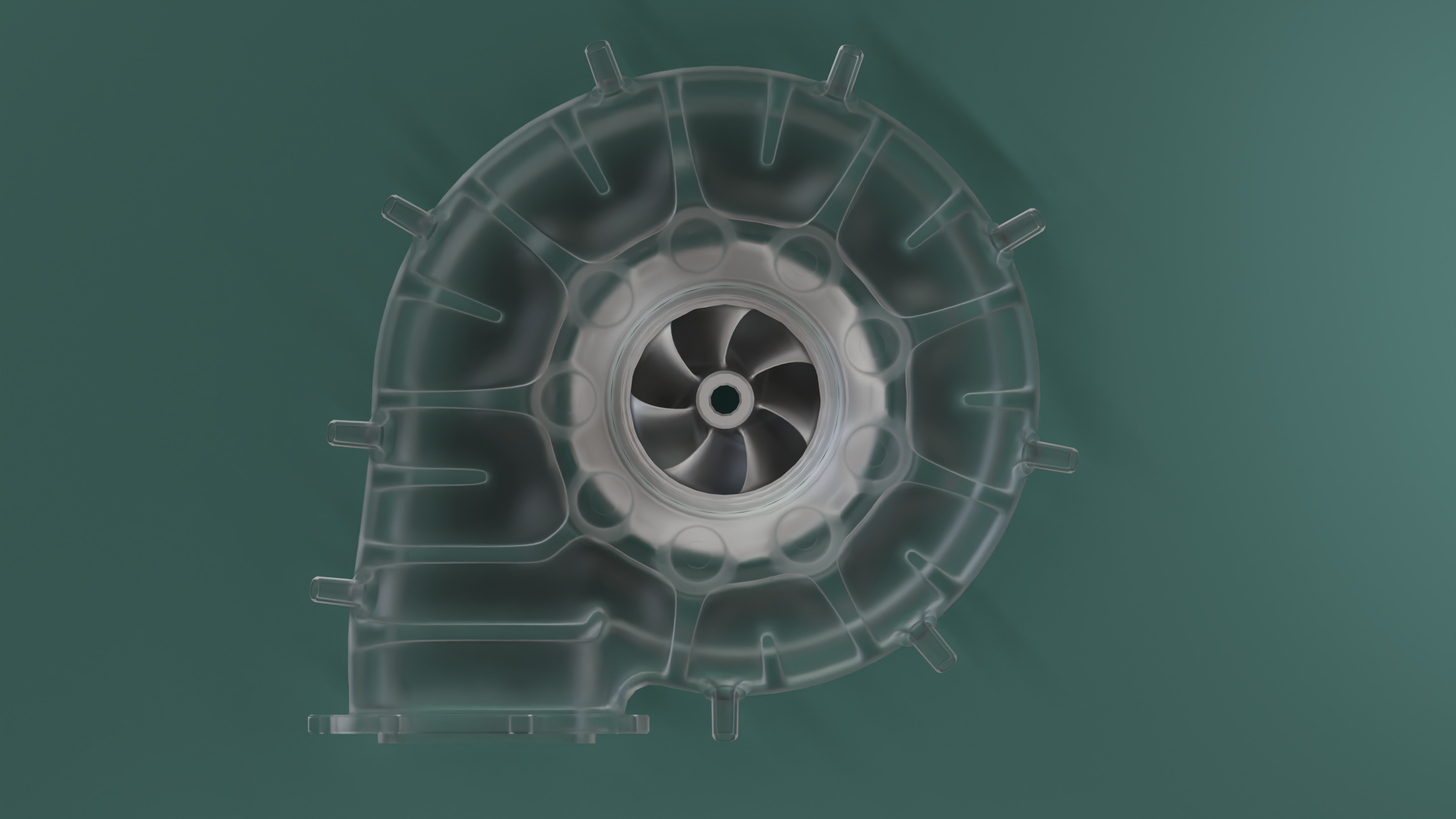
Below shows a render of the coolant passing through the channels of the pump body. The cooling system has been arranged into 9 regions - each with their own inlet and outlet. The inlet would be on the upper half of the body, whilst the outlet would be in the lower half. The intention is that plastic hosing would be connected onto these barbed fittings. This arrangement of regions was favored over having a single long channel with one inlet and one outlet, as multiple inlets around the entire pump body would ensure that each region of the pump body was receiving fresh cool water, improving the temperature distribution across the pump body. Additionally, multiple regions in this arrangement would allow for much easier powder removal after printing. Furthermore, the channel structure produces a very stiff and strong body, with the ribs also acting as a form of "heat exchanger fin".
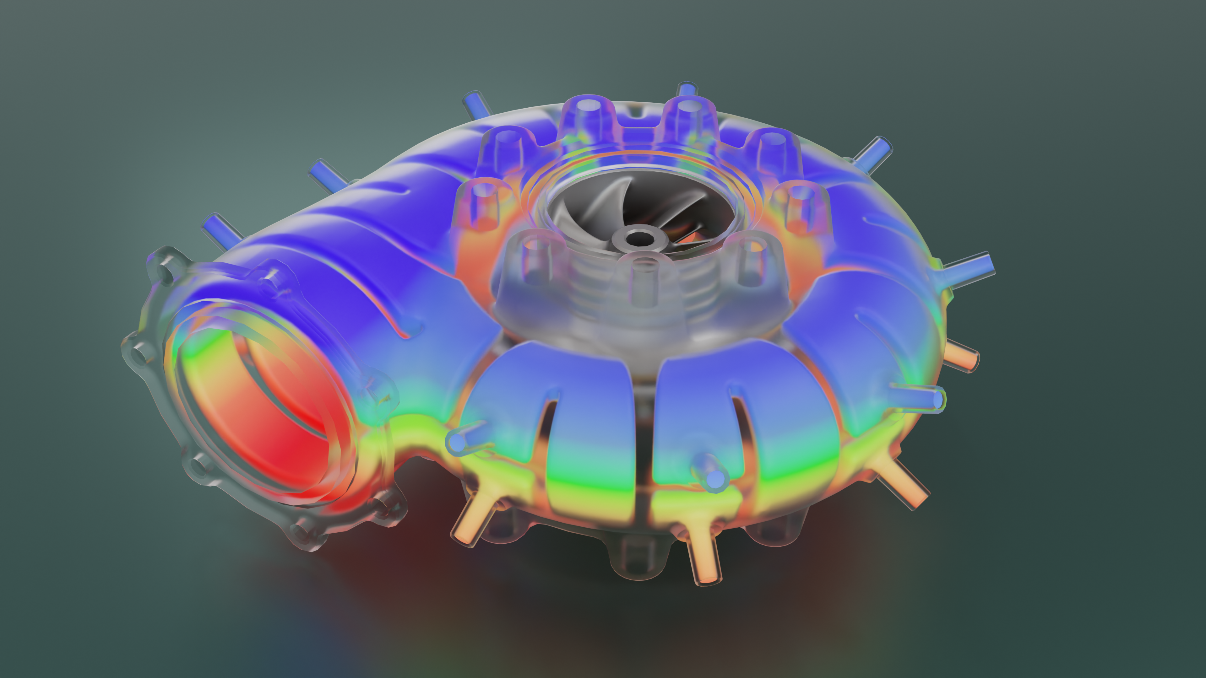
The above image shows the coolant filling the channels, with the colour indicating the cool temperature of the coolant from the inlet which then only heats up.
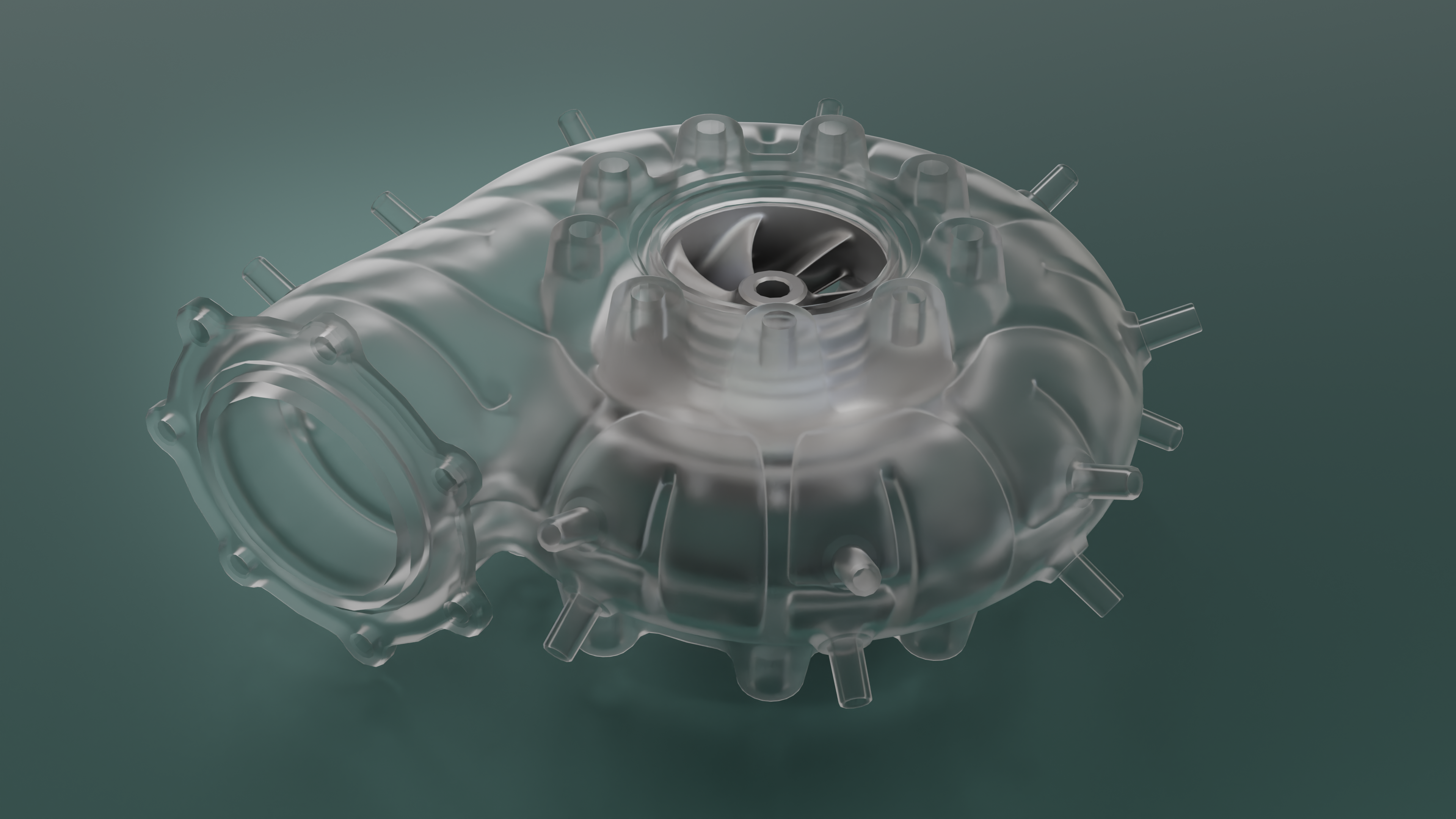
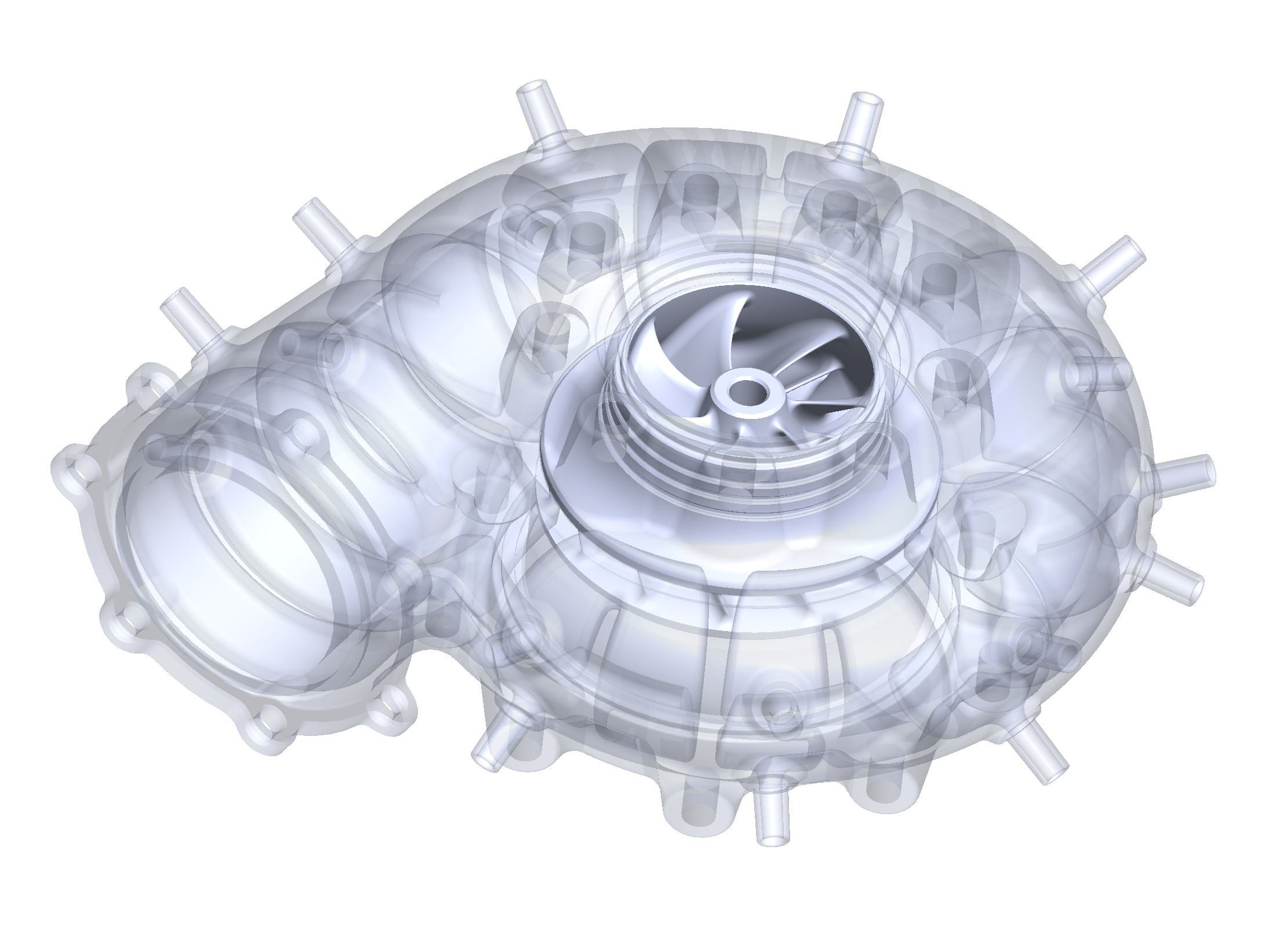
Above image shows the pump body with the coolant removed.
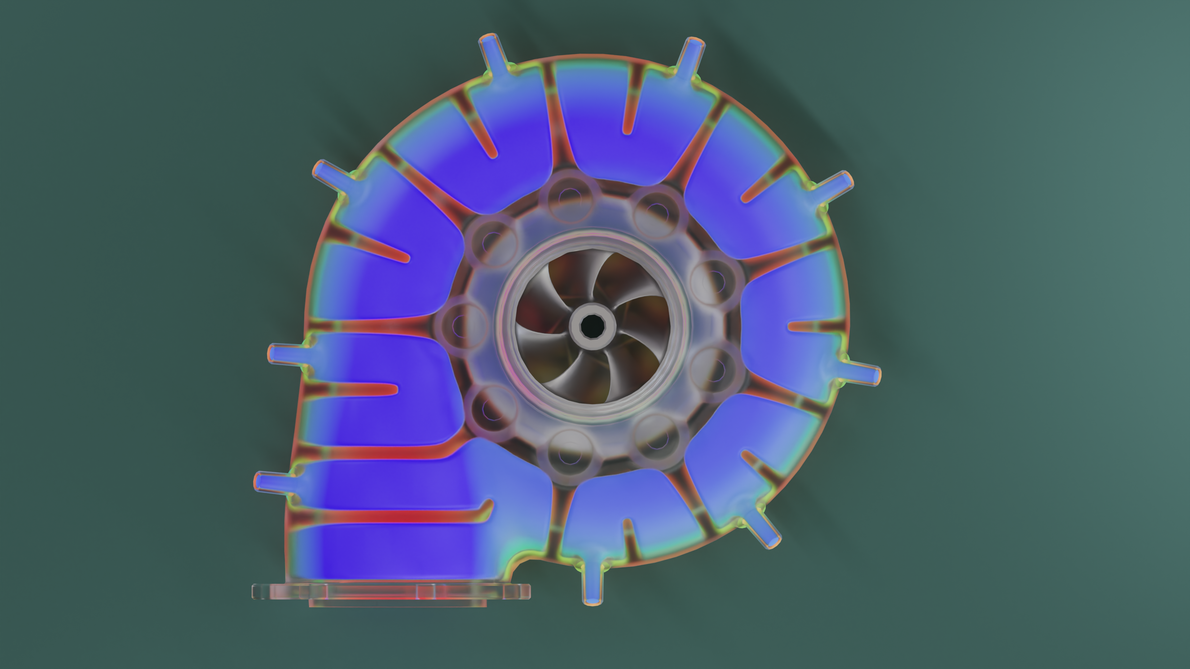
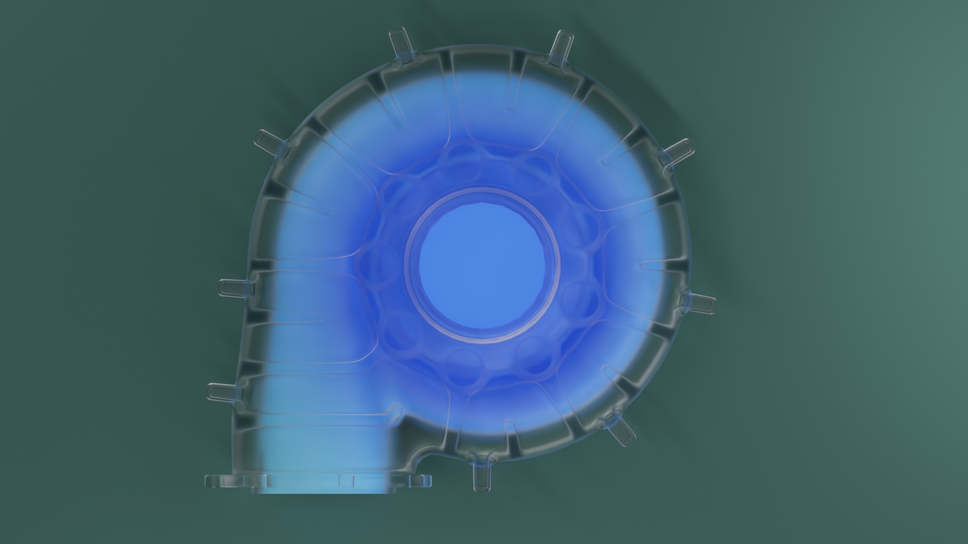
^ Above shows just the working fluid passing through the pump.
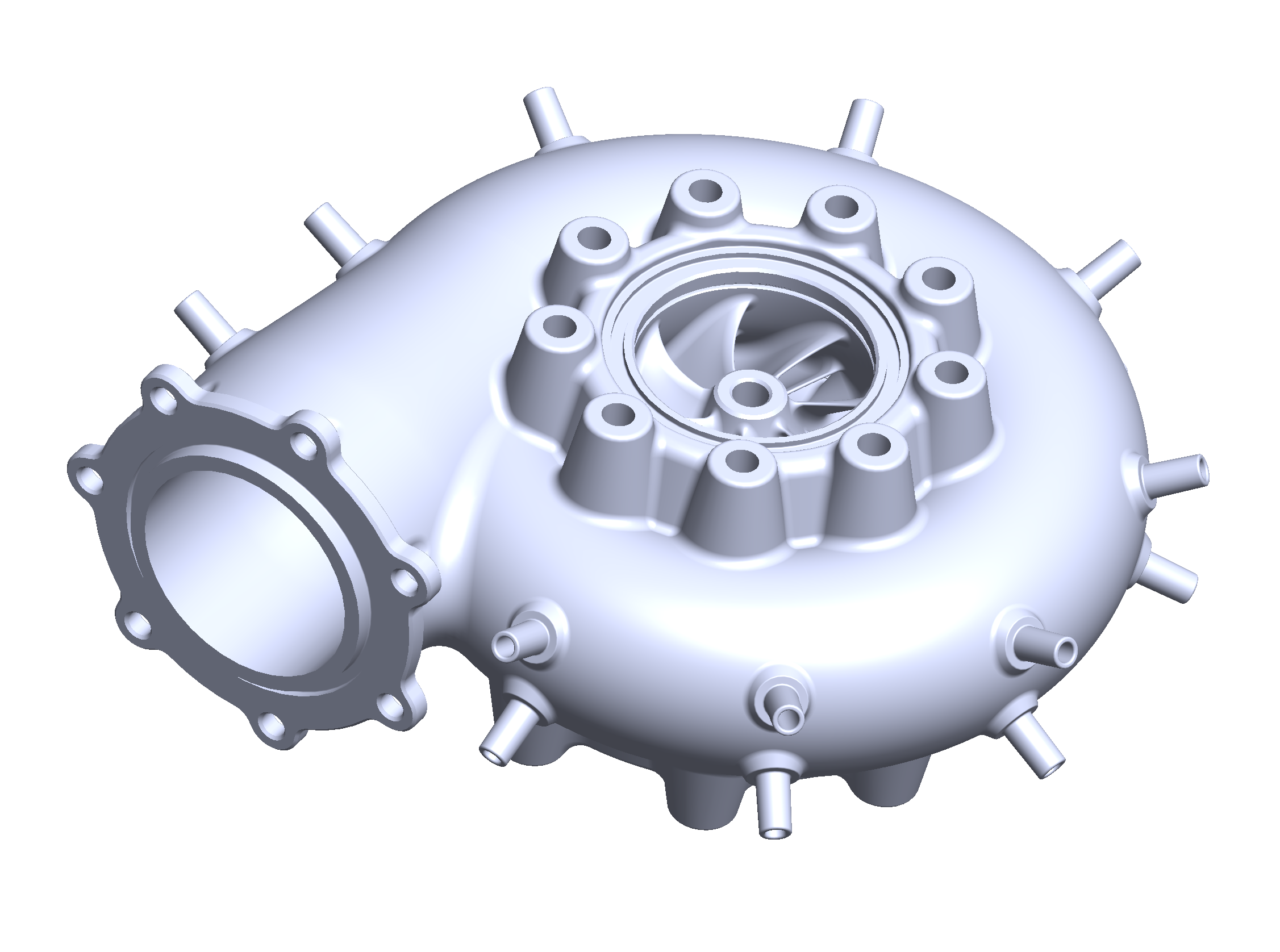
SOLIDWORKS Screenshots:
Coolant could be supplied by a separate small cheap pump, or even simply by attaching a hose to a tap. Alternatively, the main pump motor could also be used to power a small pump to run the coolant loop (though this would effect main pump performance). The coolant loop would likely also be pumping in/out of a reservoir of water. Though alternatively at higher cost, a radiator with a fan for forced convection could be equipped to create a closed loop coolant system.
Additionally, coolant would ideally also need to be supplied to a cooling-jacket around the motor to prevent overheating, as well as to the rotor shaft sealing unit.
Water Sealing:
The parts of the pump body was intended to be sealed using a silicone O-rings and/or silicone laser-cut gasket. Silicone would be the preferable material due to its high temperature resistance, but nitrile rubber can also be used here.
However, the real challenge is the sealing of the rotor shaft. In normal pumps that deal with room-temperature fluids, special sealant can be employed to seal the shaft. But this unfortunately melts away at elevated temperatures, making it unviable for this project. Hot fluid pumps have to instead make use of mechanical seals. These are costly and expensive to purchase, and too complex to manufacture ourselves. Additionally, the shaft will be spinning in excess of 10krpm, making other alternative sealing methods unsuitable. In the end I settled on the idea of making use of a rudimentary labyrinth seal. This could be manufactured ourselves on the workshop's lathes. Whilst this won't seal the shaft perfectly, it'll help significantly, and excess fluid can be drained away in the seal section of the design.
Transmission:
The motor available was a inrunner bladeless motor, originally intended for an electric ducted fan. As a result, the motor was optimized moreso for achieving high RPM rather than torque. Nevertheless, with a current of 80A and 14.8V input, it's not like the motor is weak. The manufacture had not provided torque curves or any other detailed motor specifications. Anyhow, it would've been very likely that the motor would have required a geared transmission.
Conclusion:
This project was never fully designed or manufactured as a result. The team was able to source a pair of gear pumps that were able to provide 14L/min of hot water from one of the department's labs. Whilst, this did not meet the minimum engine coolant flow rate, we felt this was sufficient for our testing. Thus, we felt that it was no longer needed to pursue designing our own pump. Especially, as this would be privy to complications and additional costs & time.
However, if this pump design went ahead and were successful, this would have provided the team with a cheaper pump than 3rd party pumps, whilst also being able to test for a much wider and higher flow rate range - realistic to that of the engine.